Integrating 3d printing with off-the-shelf parts. This page is for examples that integrate 3D printing with OTS parts. I'll call it printegrating, to set apart these designs from all the world's 3D printed parts.
Problem 1 Designers are uninformed in design-for-manufacturing in FDM; these examples show how. Designers need modularity to raise effort on each piece of a design. These examples demonstrate demonstrate modularity. Designers are unaware of the best off-the-shelf components; these examples highlight suitable components. Designers are reinventing the same designs; these designs aim for best-in-class quality.
Problem 2 Open Source Parts must be adjustable; these open parts are adjustable. Parametric parts lack instruction on how to adjust parameters; these examples indicate how to adjust them. Open designs only suit a specific need; these examples are versatile.
Value Printegrated parts are the optimal type of part to open source; the most leveraged way for designers to create value. Compared to a parametric part, we double the value by including parameters which are derived from the mating part. Compared with plain prints, they capture the qualities of a metal part. They intrinsically reduce the time and material for printing. They spur ideas because the audience is familiar with the 50-year-old part. To support engineering research, the assembled printegrations carry documentation produced by the manufacturers of the off-the-shelf parts. To support evaluation, the OTS parts carry certifications & testing metrics.
MMET Students & Professors: As your Technical Laboratory Coordinator I would like to construct a display of several of these relevant parts for hands-on inspection & discovery of the design methods to make these designs. I got approval in 2025 October and I'll aim to build this demo over the next few months. These should help with: how to design printable parts, and how to utilize versatile materials to reduce my design effort.
Sleeve
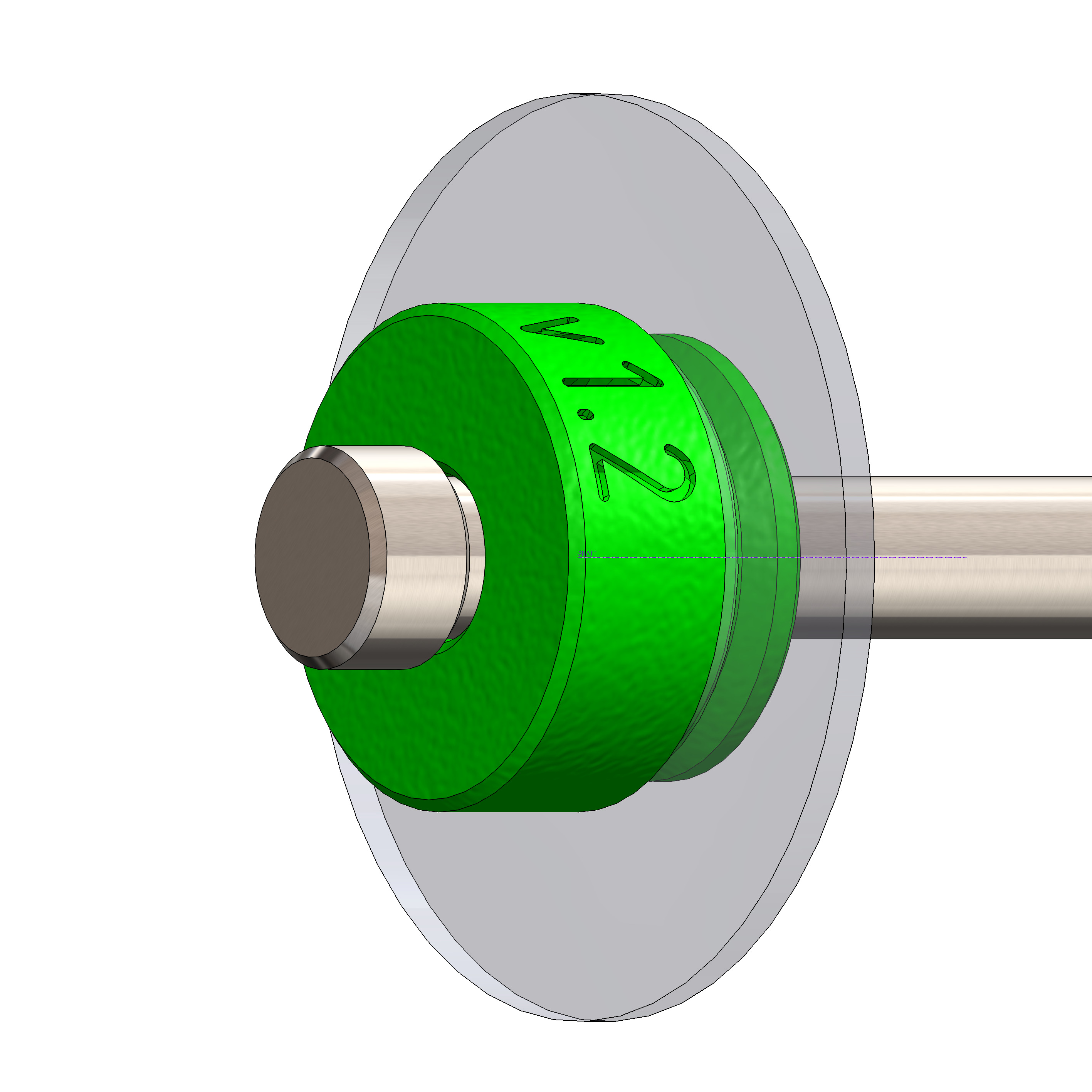
An adapter for a shaft in a thin wall. Use two sleeves to support a loaded rotating shaft for a range of needs. The first version has a slip fitment for a bolt, another version which carries a bearing (8mm), and lastly version with imperial 1/2in bearing. For retaining the sleeve, we can use a retaining ring (e-clip) or an o-ring. The shaft can be centered, offset by 3mm, or adjusted with a parametric offset. Having an offset shaft gives a range of adjustment for fitting a belt. In the example, we couple two parallel shafts with a chain, belt, or pulley. This model has a higher investment in documentation as an example parametric part, having a tree of parameters that lead to multiple files and use cases.
- Access the sleeve CAD Model
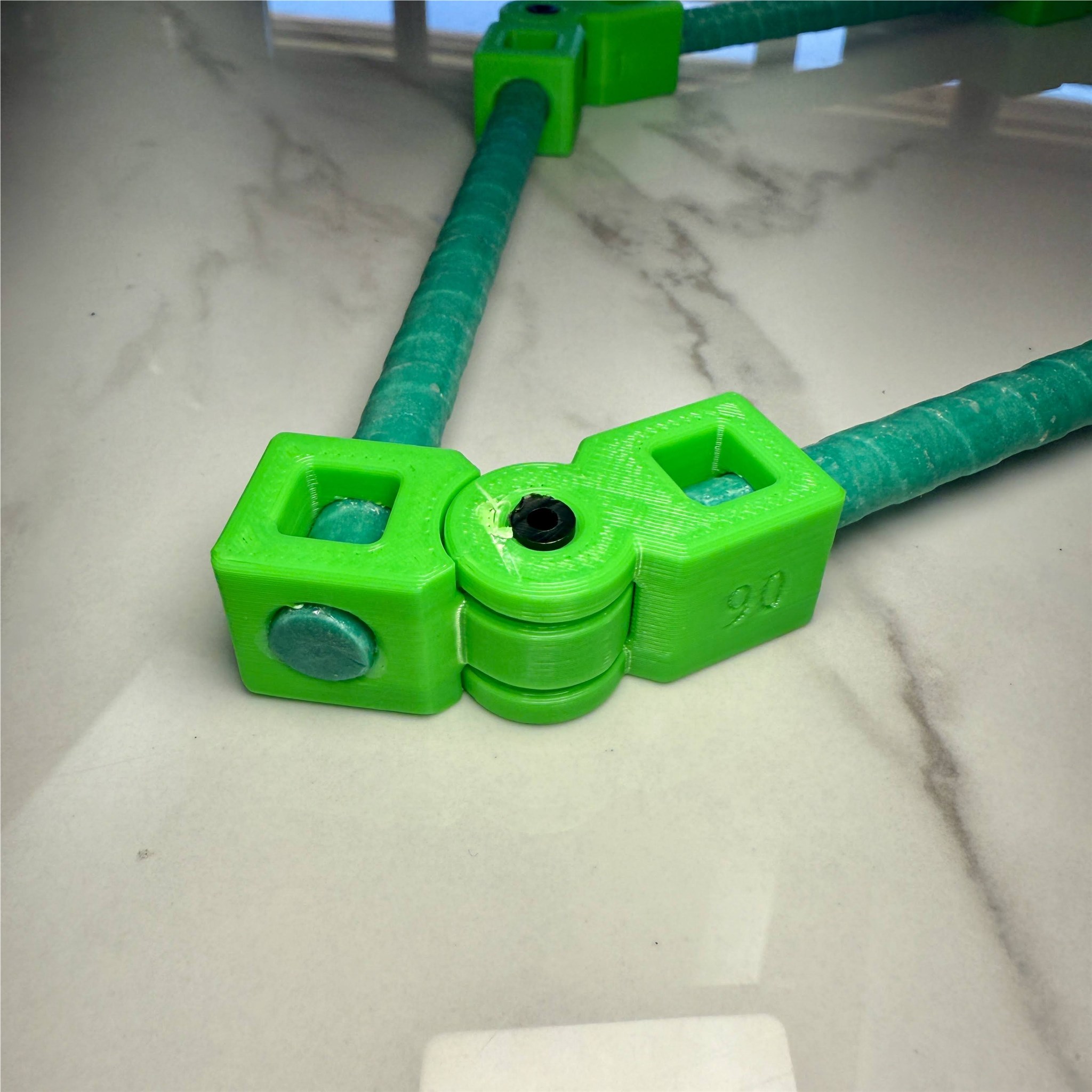
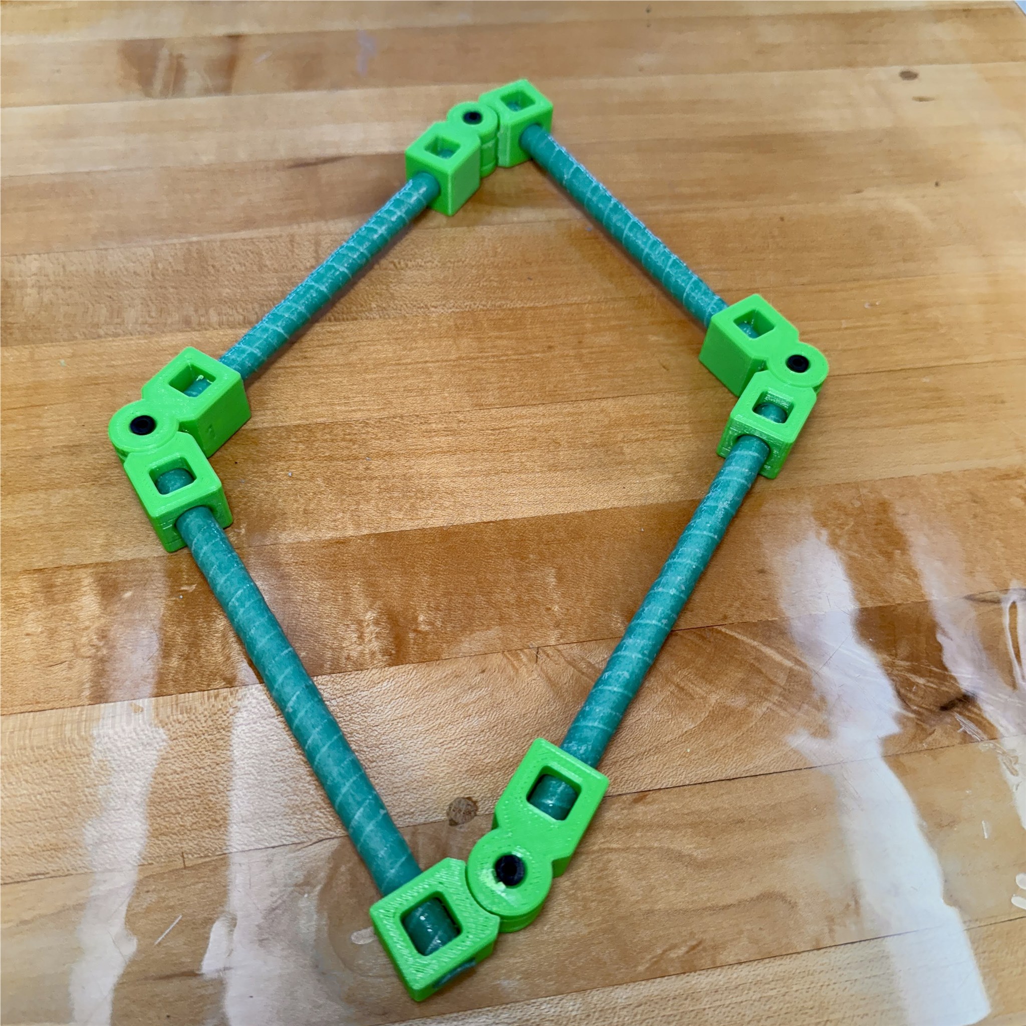
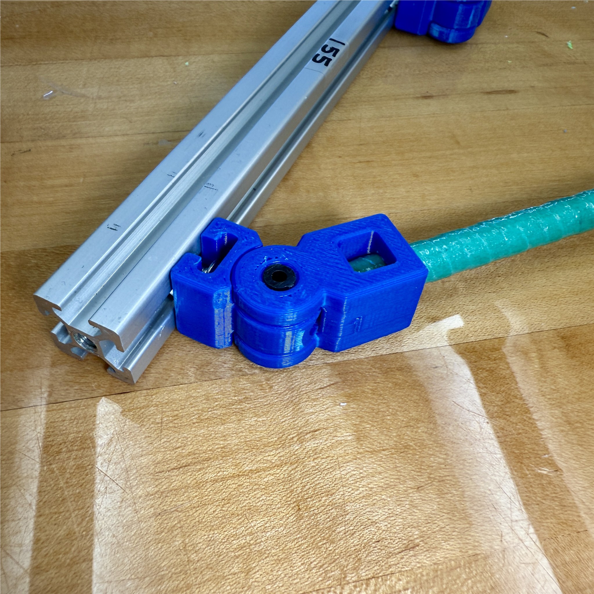
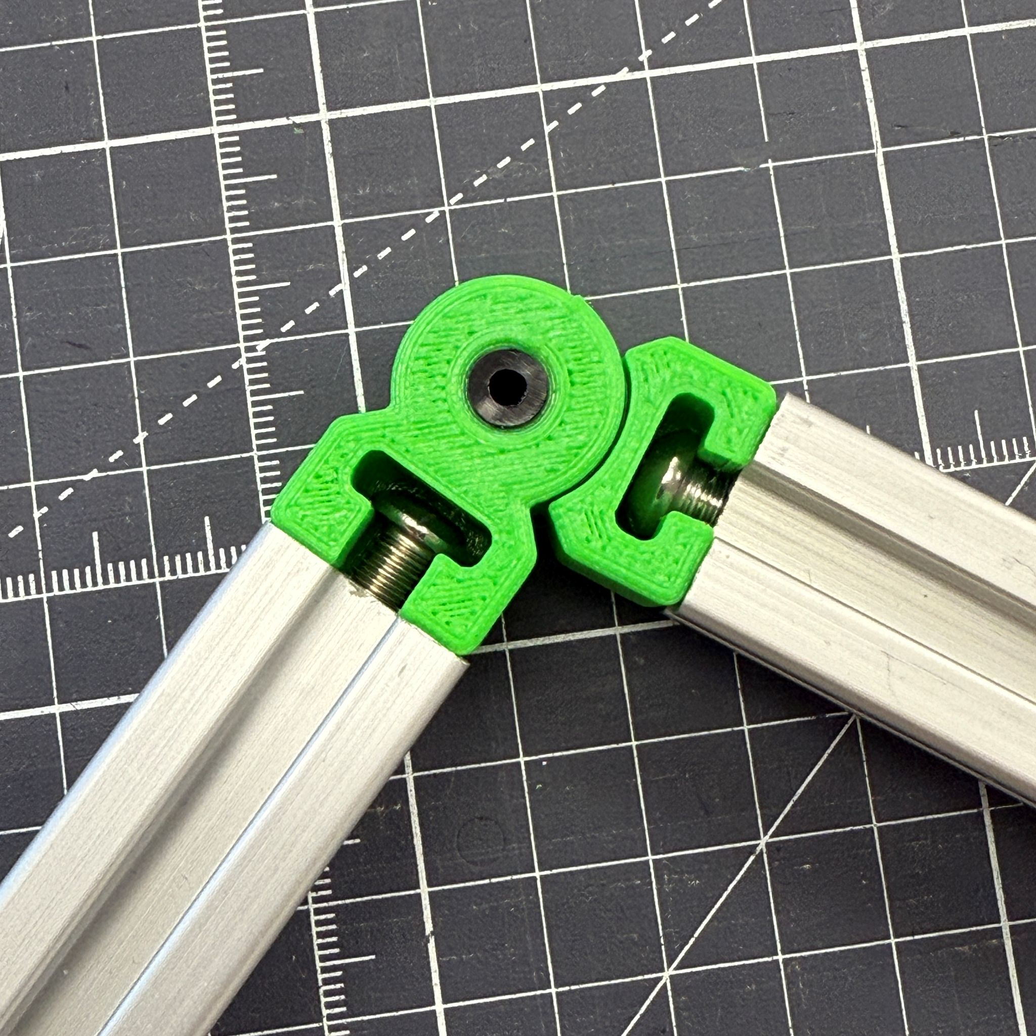
HingeRod
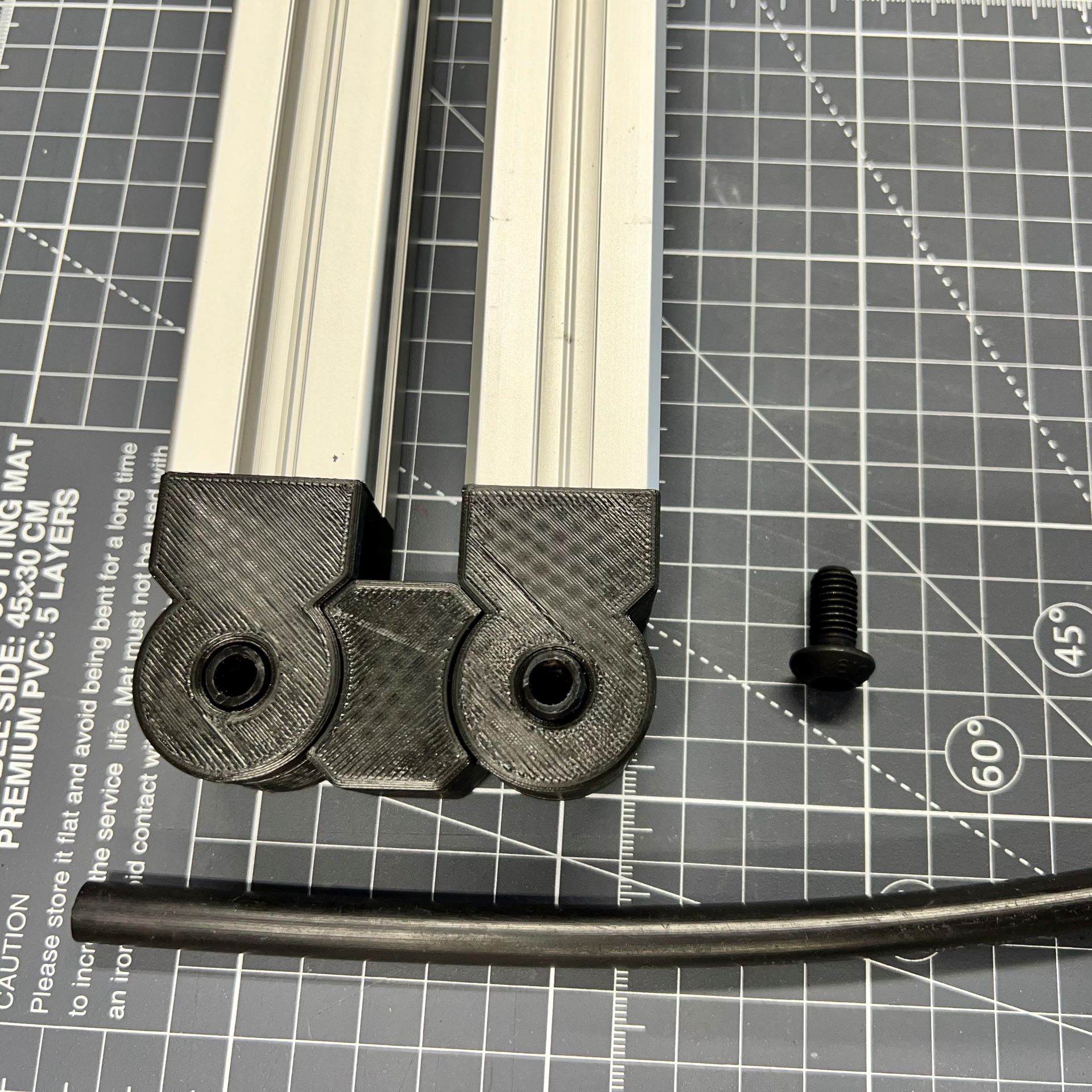
A printable joint or hinge for fiberglass rods, approx 10mm diameter or 3/8in trade size. The swing is +/- 90 degrees and one model is centered at 180 while the other is centered at 90 degrees. The fiberglass fits with a light press and bonds with some superglue (CA glue) that wicks in between the faces. Just like several other hinge parts, you can use a 6mm HDPE tube for the hinge pin or M6 size of fastener, or 1/4in clevis pin. Three solidworks models post are hingeRod, hingeRod_90, and finally hingeRod20 (with one end fitting to 2020 extrusion). See the third photo with hingerod20, connecting fiberglass rebar to aluminum channel.
- Access the hingeRod 3D model on grabCAD
- See the youtube short video here demonstrating the assembly.
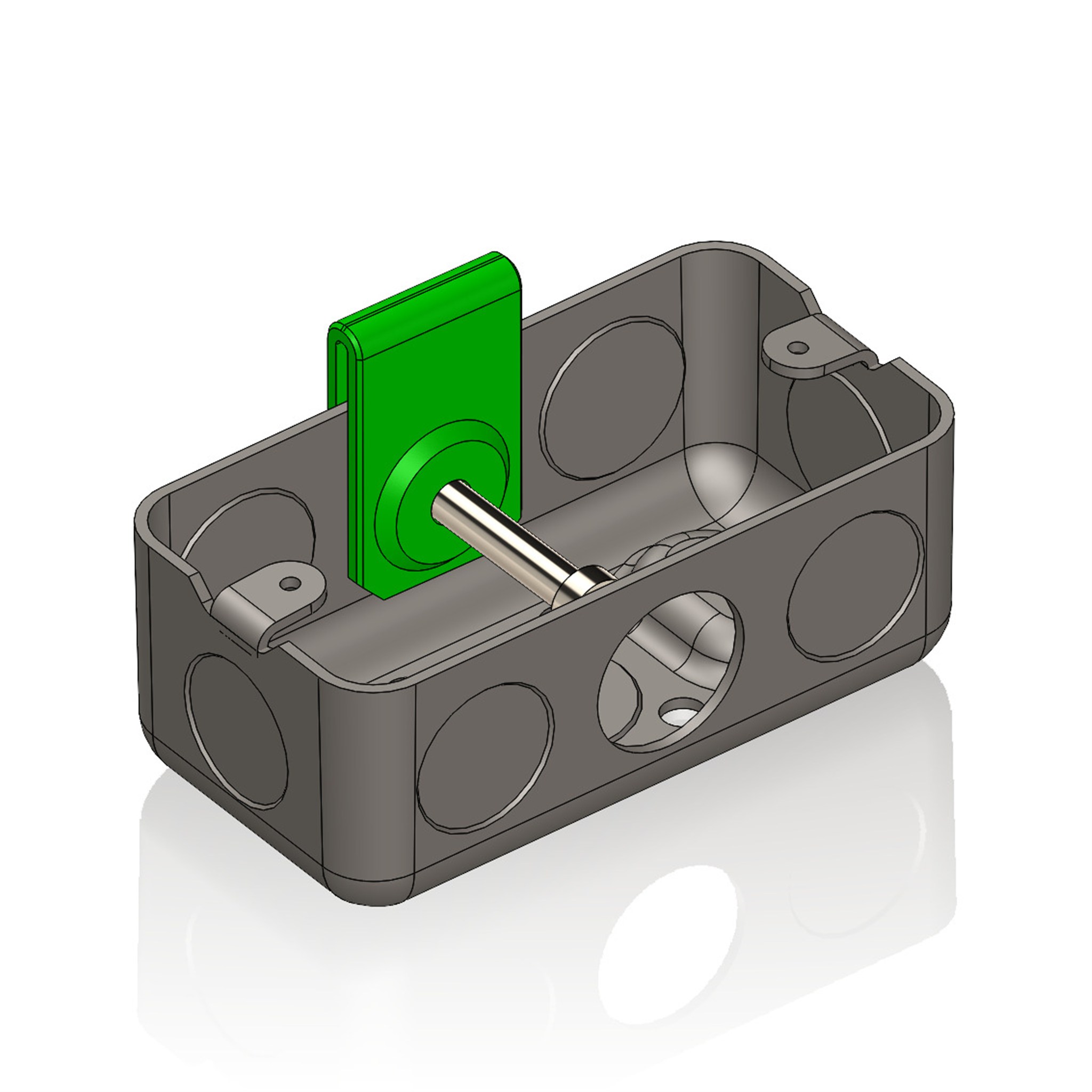
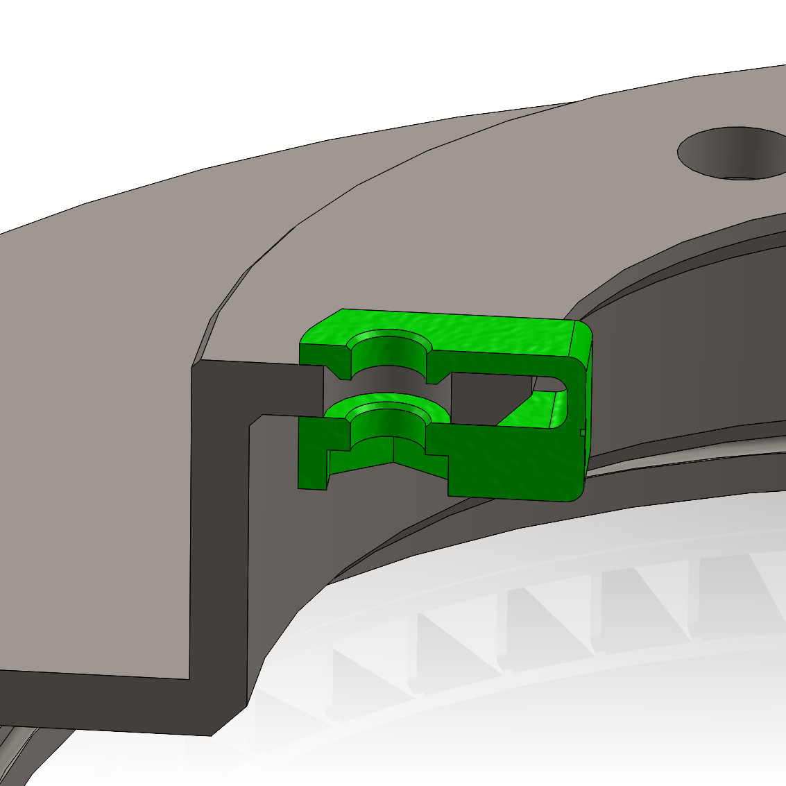
Reducer
An example part for reducing a hole to host a fastener. One example is to outfit concentric shafts in a steel outlet box to achieve nicely-aligned axes in a gearbox. The second example offers a location for M8 fastener in a large 14mm hole of a disc brake. Utility aside, it's a lesson in compliant mechanisms, gaining concentricity, bearing loads on a 3D printed part, retaining a steel nut with friction.
- Jump to grabCAD post:reducer model

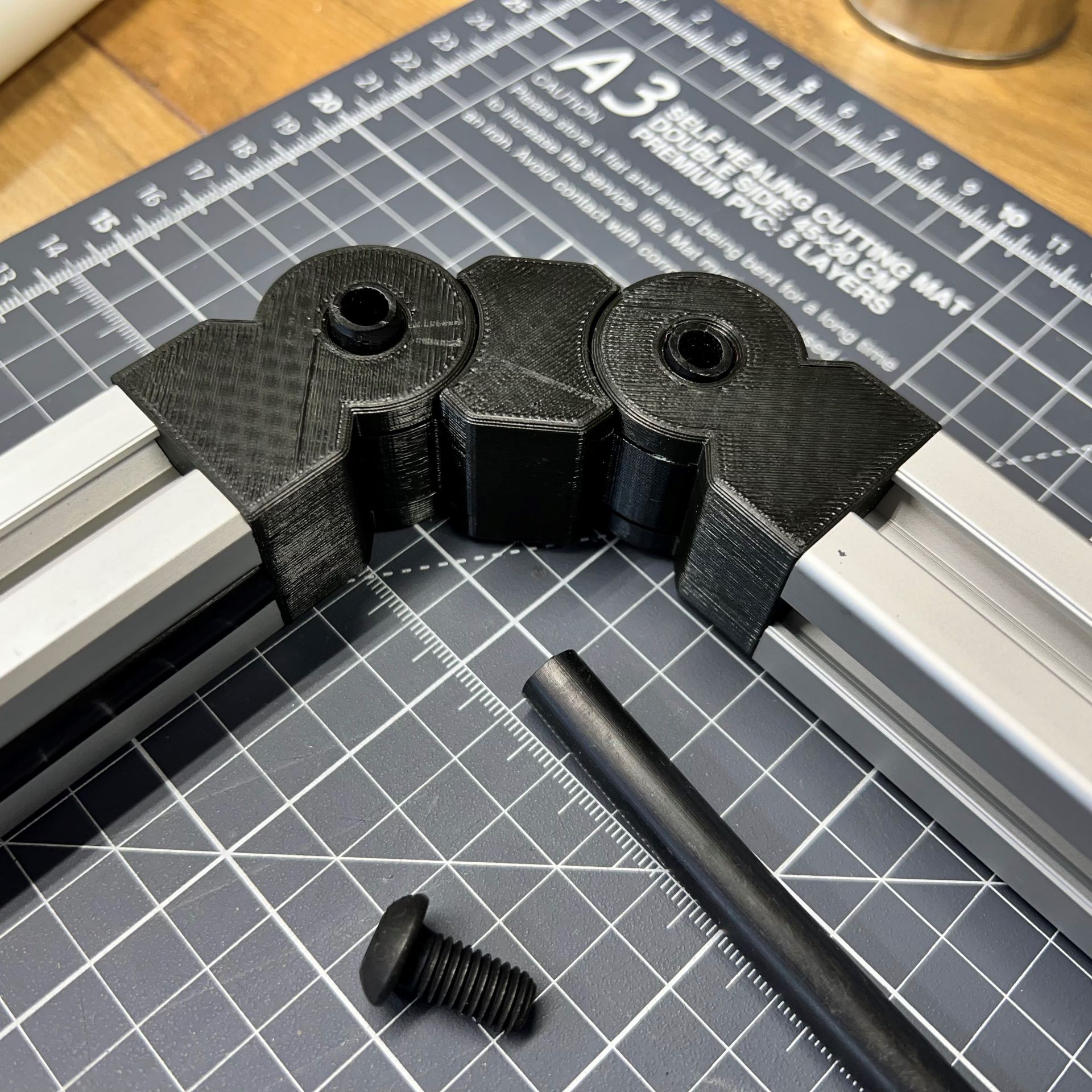
Hinge_End
Printable and print-in-place design for a hinge for 2020 extrusions. Tap M6 threads in a 2020 extrusion or mount to the side of the extrusion with M5x10mm fastener as usual. The hinge pin uses 1/4 or 6mm stock such as HDPE tubing, or a simple steel clevis pin. The hinge model is highly parametric and many variations are possible. Note the limits on the rotation built into the model. The rotation stops at +90 or -90 for the template parts. Important templates include hingeEnd for extrusion ends, hinge30 for 3030 extrusions, and hingeRod for joining 10mm rebar to the assembly. The name has updated to "hingeEnd20" in some files because this design was also produced for 30mm extrusion, and round stock.
- Model for hinge_end here
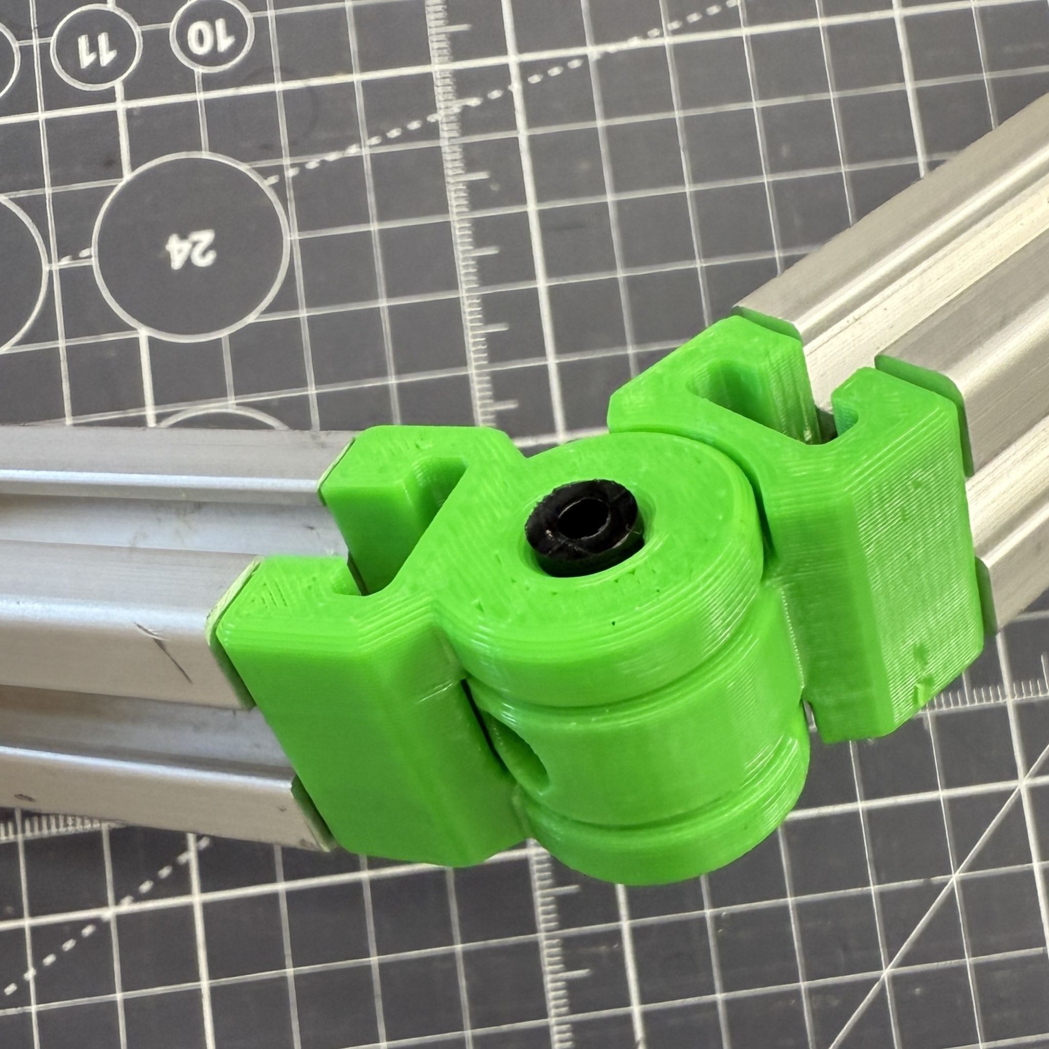

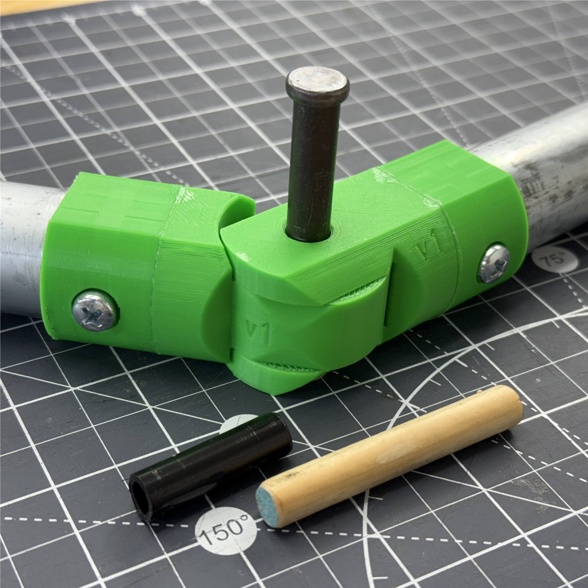
PivotBeam
This double-hinge model predates the hinge designs for 2020 extrusion, and uses a 3/8 pin instead of the smaller 1/4 pin. Again, the common LDPE tubing for water distribution fits in this design. The hinge has 2DOF which means the strategy for CAD modeling is rebuilt from the beginning of the feature tree, compared with other hinge parts. The model will print-in-place without supports, and produce three separate but interlinking bodies.
- Model for pivotbeam on GrabCAD

HingeRound
A special variation of the hinge which connects round tube. The initial version works with 29mm OD tube, found in EMT Conduit of 1" trade-size. This assembly consists of two CAD models: one for the hinge and one for the collars. With this configuration, the collars are printed in an optional z-direction for speed and strength, while the hinge prints with two interconnected bodies, ready for pin-insert and snap-apart. You can use superglue for a permanent bond between the ABS components, with a strong seam visible in the photos. Alternatively, you can revise the main model to include the collar. To raise the strength: add a metal hinge pin, raise the hinge-pin diameter, and increase exterior diameter of the bodies overall. Several further changes are ready: add more fasteners to distribute load on the plastic if you intend to subject a strong pulling. Note the flat faces on the round body; these are for improved printing performance, and creating a datum for marking and setup of the assembly. It's recommended to keep this flat region as it assists along several steps in building.
- download Hingeround CAD model
- buy tubing, LDPE on Amazon for just $11
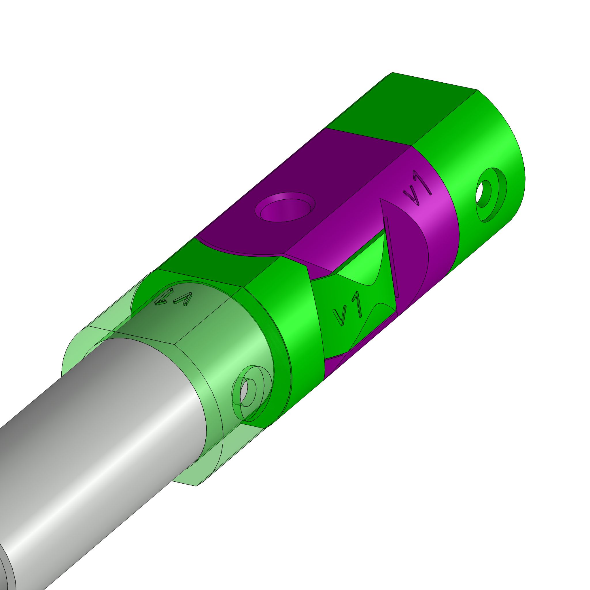
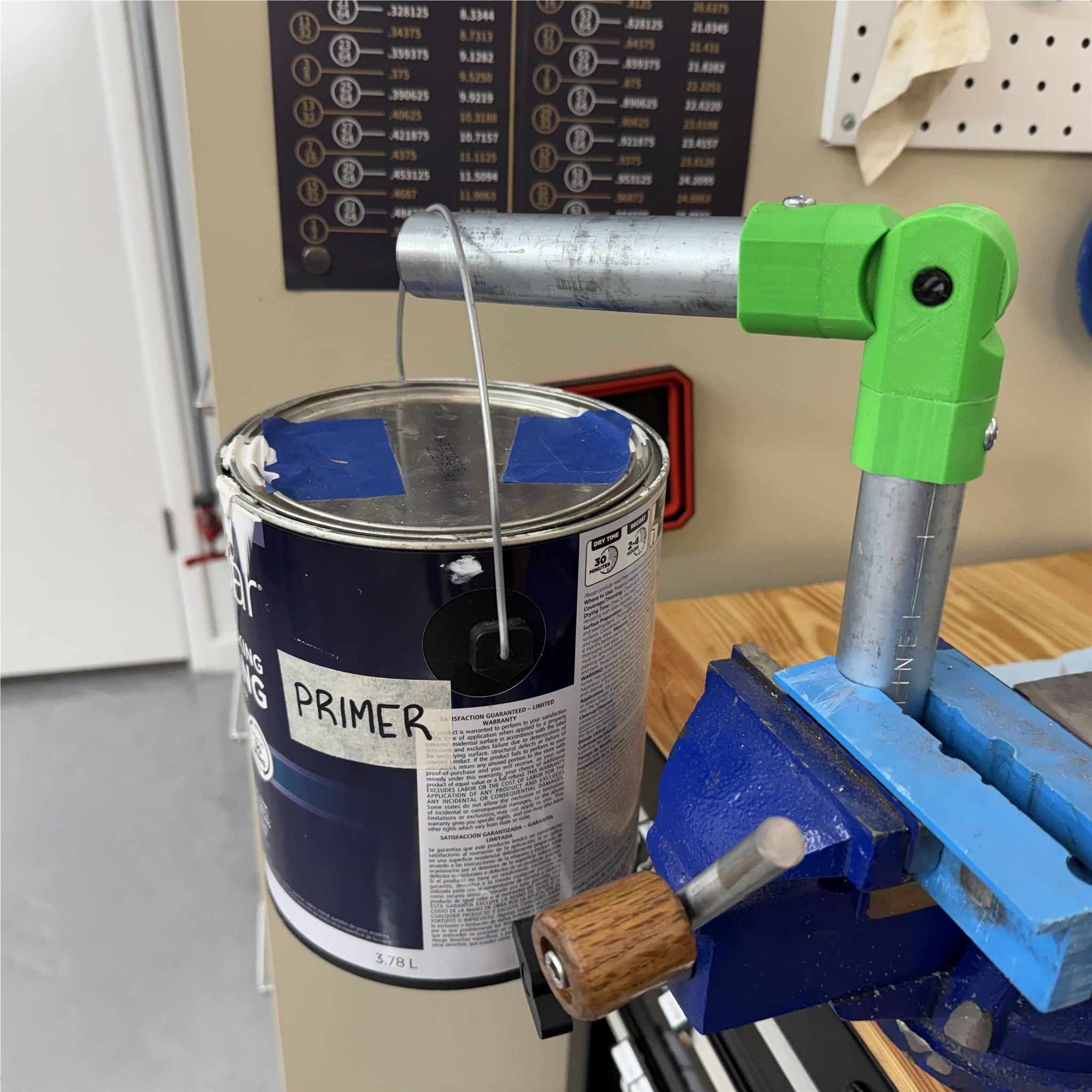
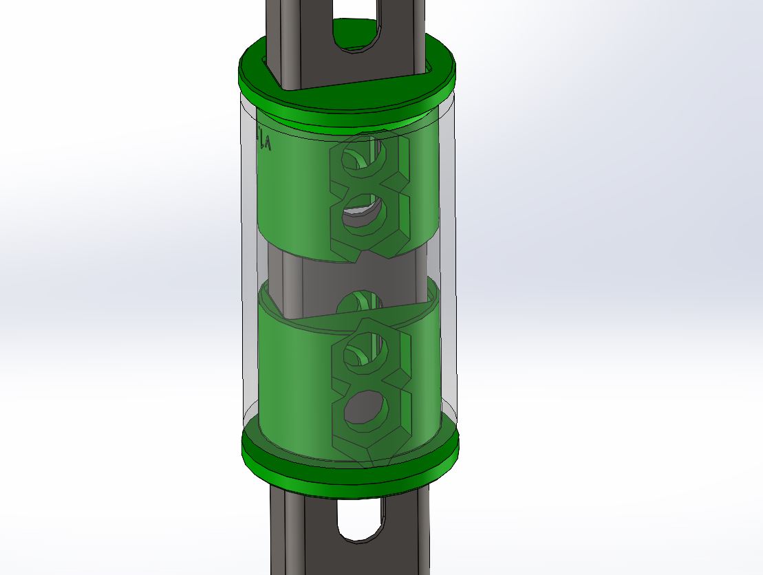
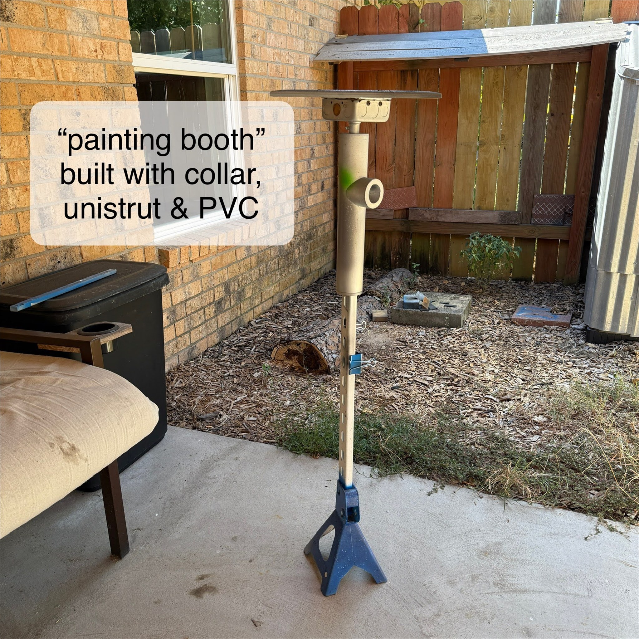
Collar
This is a simple concept of gaining a concentric mate of round stock and unistrut steel channel. The example features 2-in PVC, schedule 40, and the collar set up to carry the weight of PVC while allowing it to turn.
- download model for unistrut collar here
- watch short video on youtube for collar usage here.

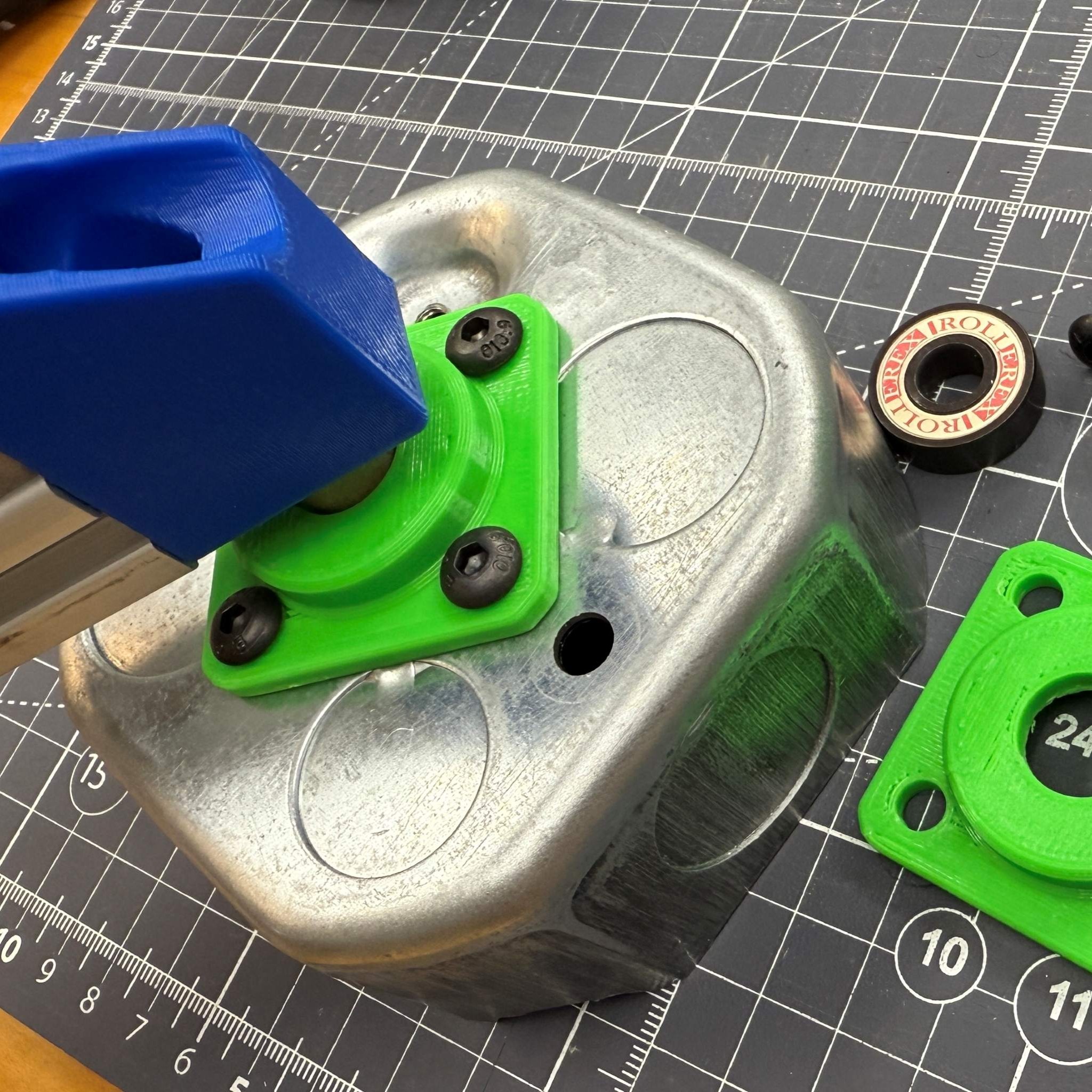
Hub
Model and tutorial for integrating a bearing in a 3D print. This model features two integrations: The bearing and the steel octagon box are both integrated and the hub becomes a joining feature between two highly-useful parts. See images below featuring M5 machine screws, hex nuts, octagon handybox, and M8 screw as a shaft.
- download the Hub 3D Model on GrabCAD
- watch youtube video here which is a full tutorial for the design process.


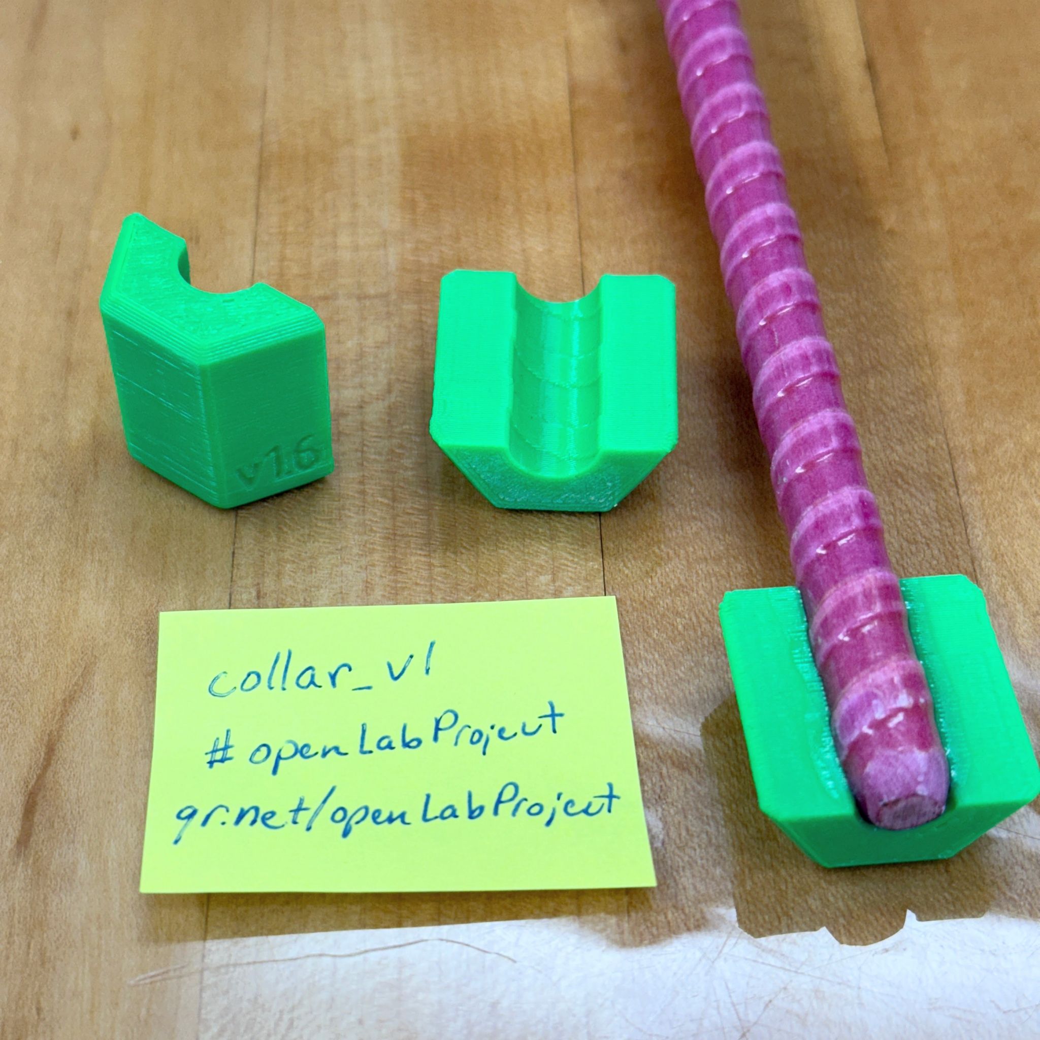
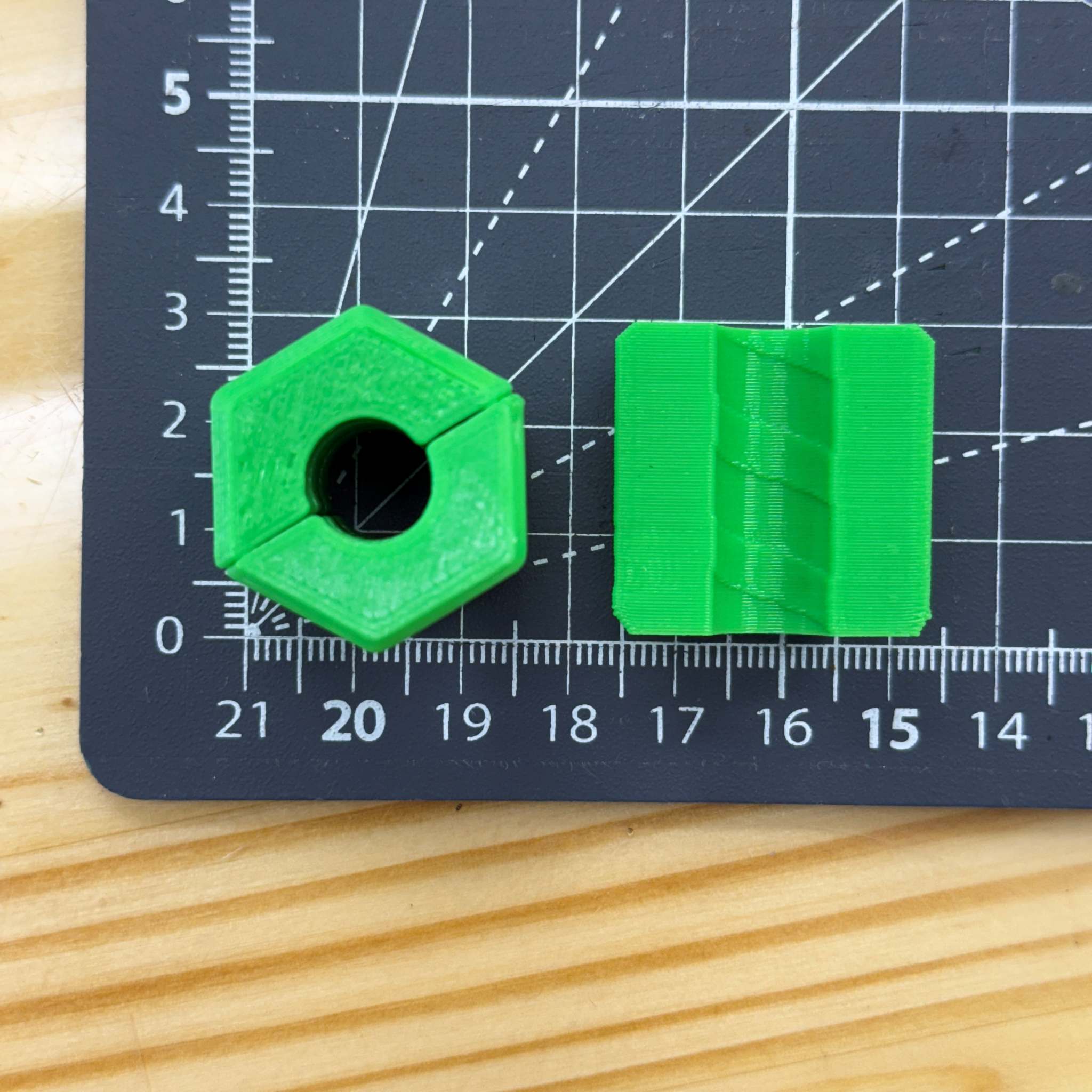
Sleeve
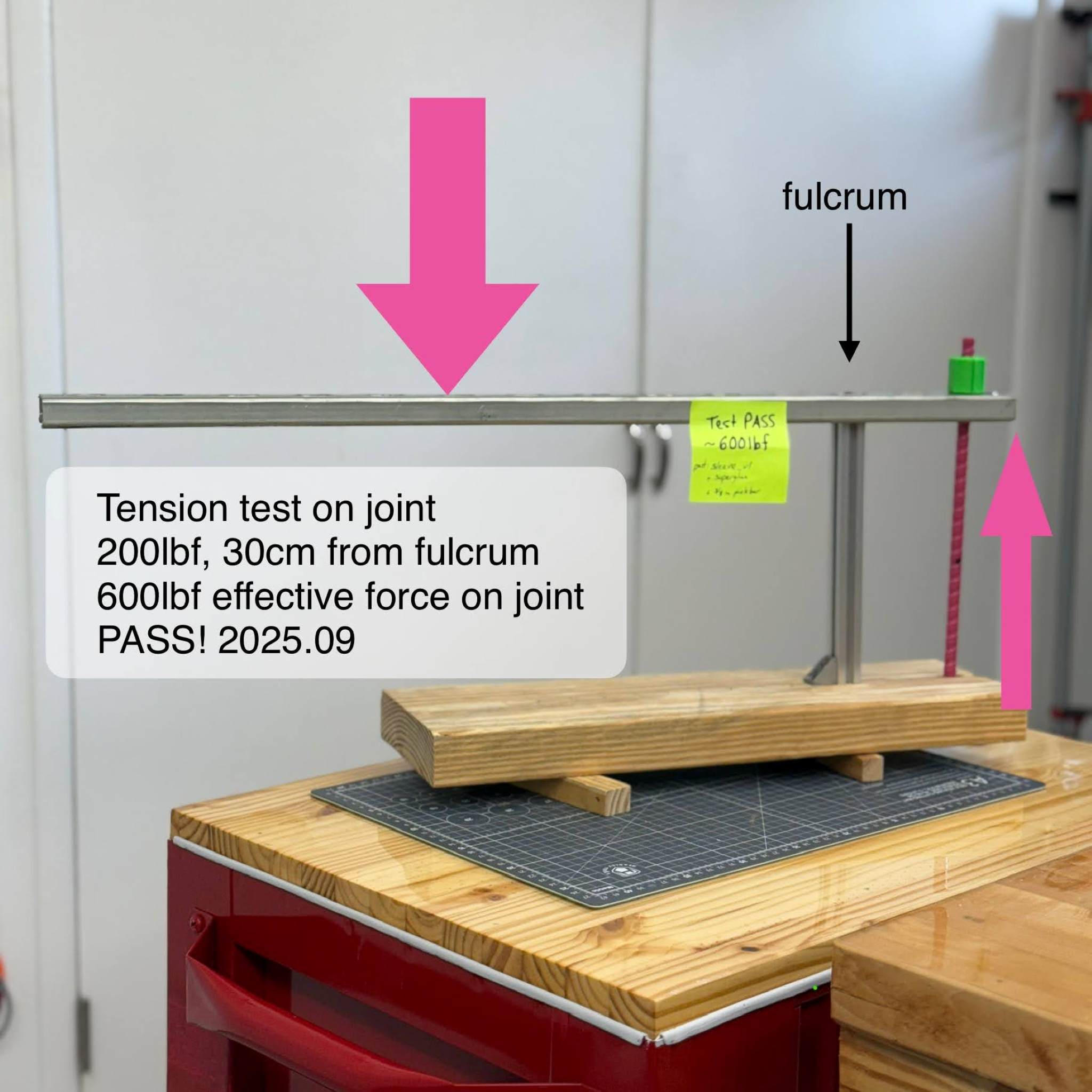
A conforming geometry for the thin spiraling boss of a fiberglass rebar. The aim of this part was to produce a strong connection to the fiberglass rebar (which has over 15,000lbs or 67 KN tensile strength) so that we can print connections and utilize this strength in our assemblies. The bar and sleeve (previously called "collar") was superglued and tested to 600lbs of pulling force without any signs of damage. Get the Sleeve CAD model here..
- watch the youtube short, introducing the rebar material
- watch the youtube short, demonstrating beam reinforcement with pinkbar
- watch the youtube short, testing tensile strength of sleeve joint
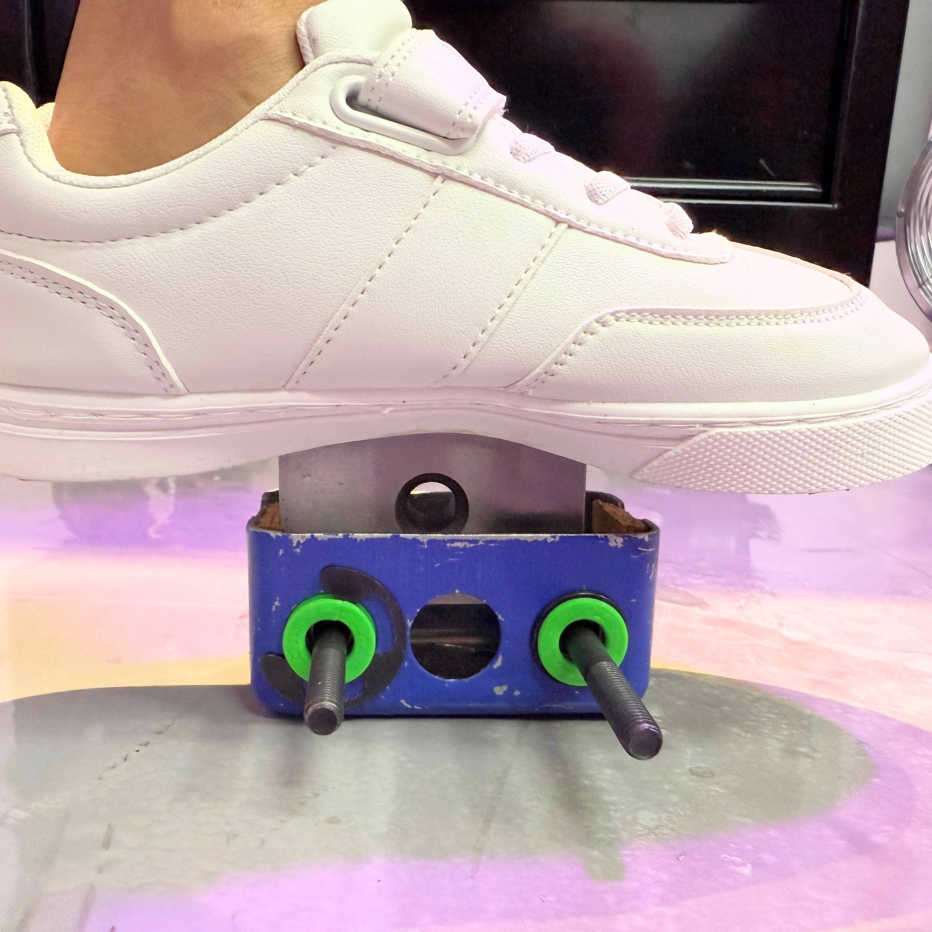
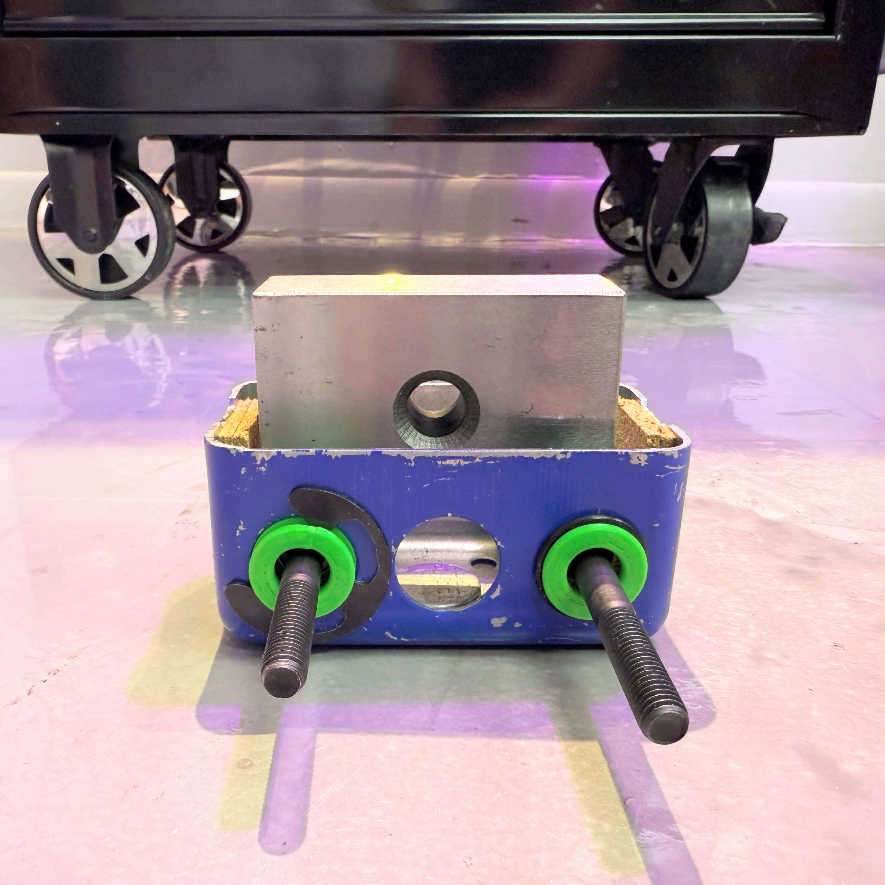
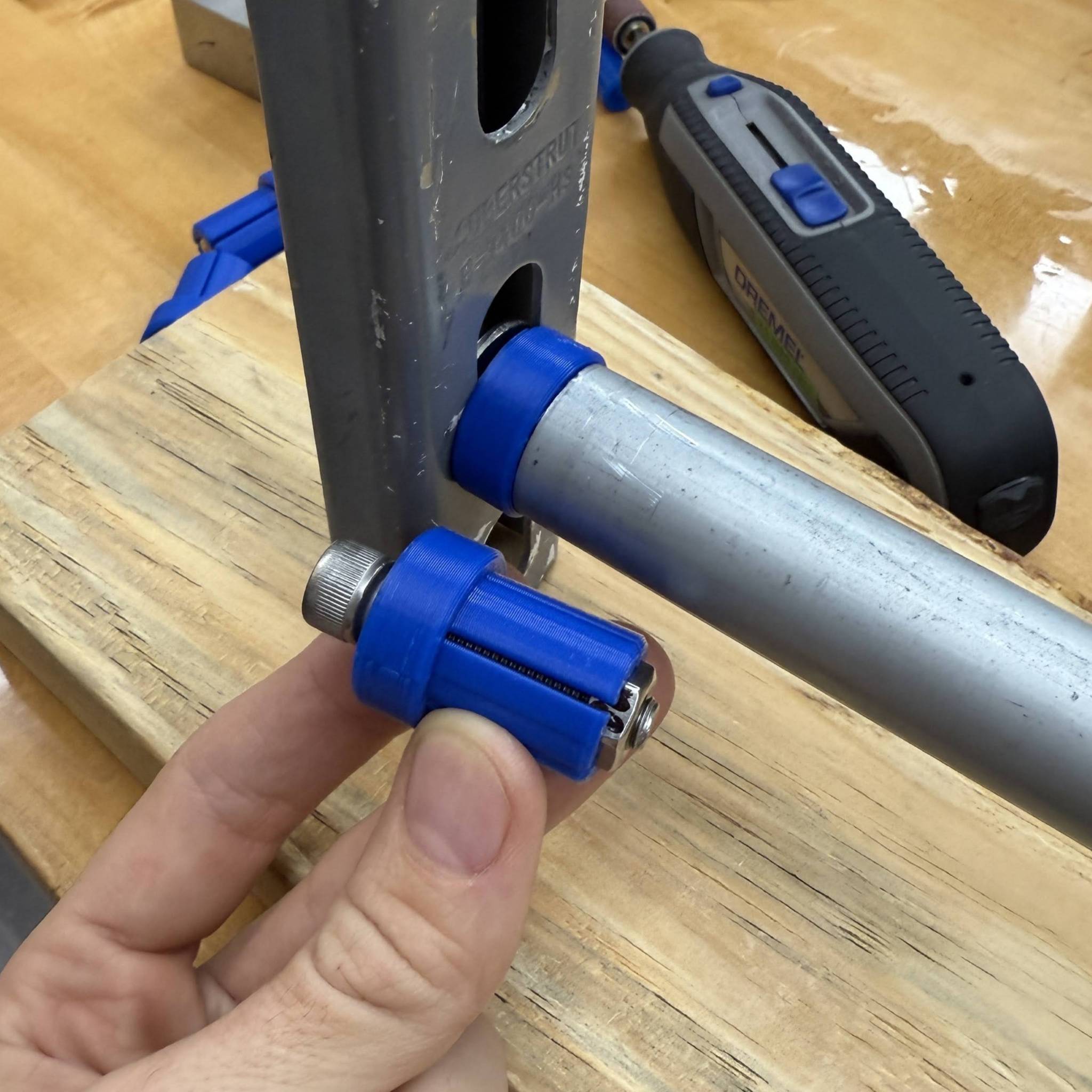
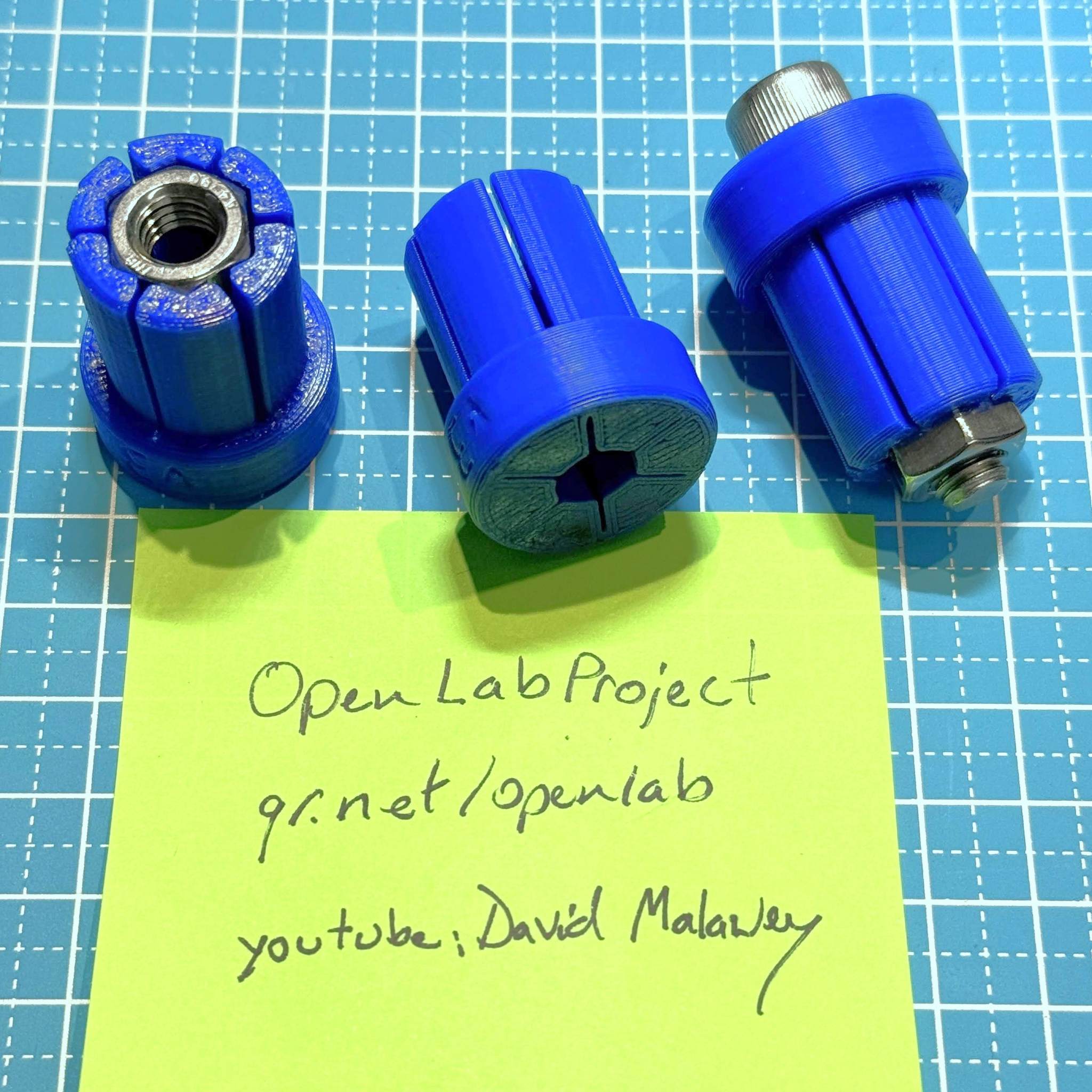
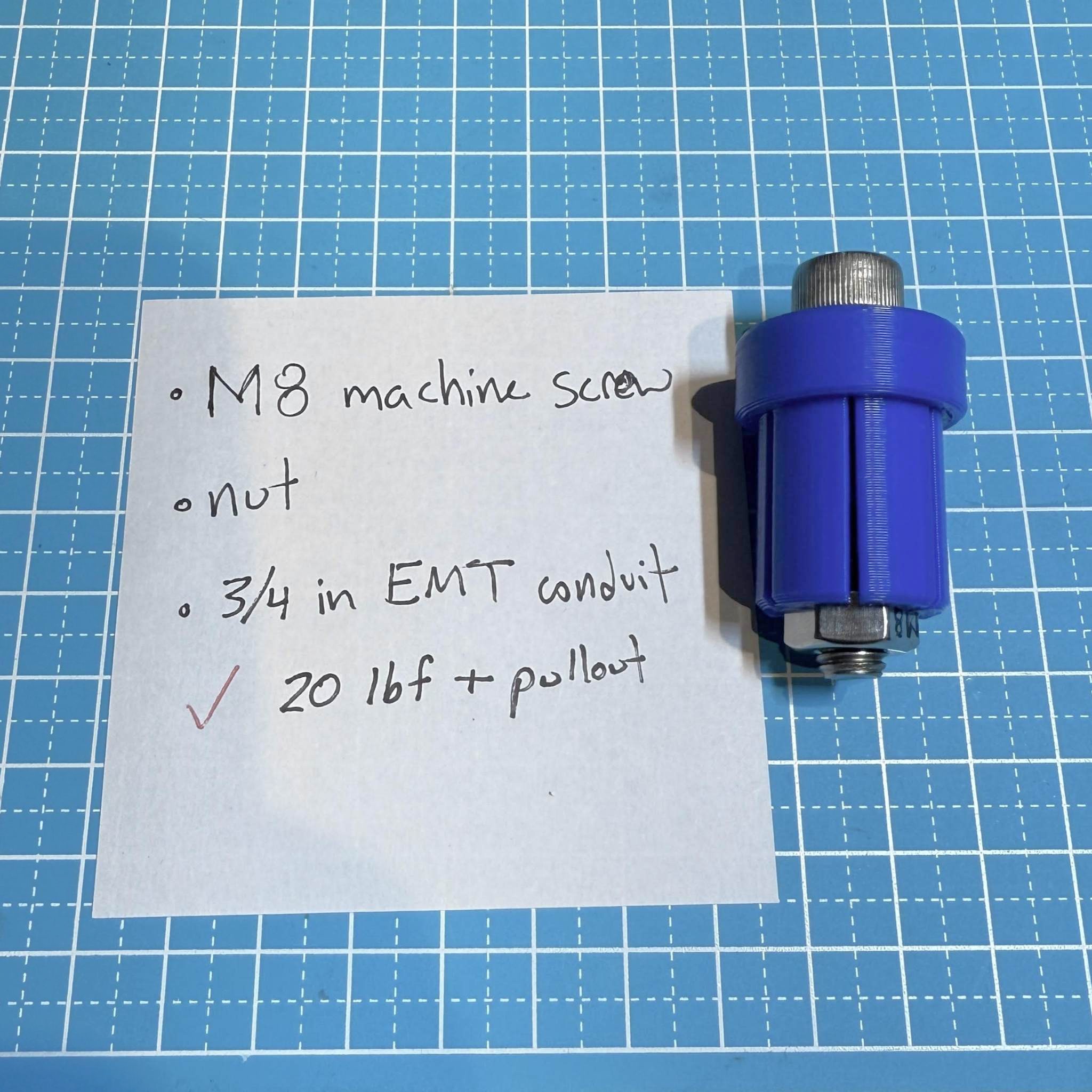
Mandrel
A load-bearing part to secure a steel rod at the end. The mandrel carries a nut (M8 hex nut), then inserts into round tube, then expands when tightened. The mandrel compresses against the tube inside, generating friction to prevent spinning of the tube. The fastener can pull the mandrel tightly against a flat surface with a hole. One asseembly is demonstrated which connects the tube at 90 degrees to a steel channel (unistrut).
- download the Mandrel CAD model here
- watch video on youtube for mandrel
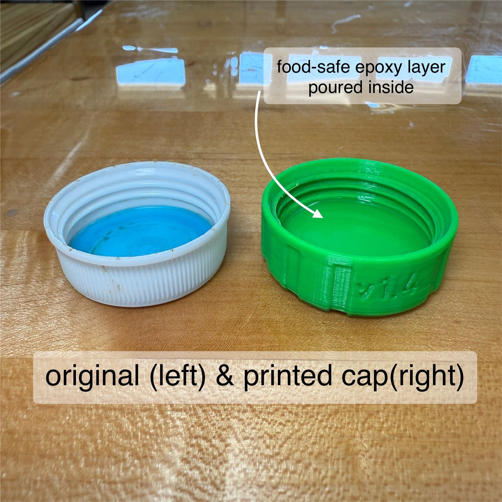
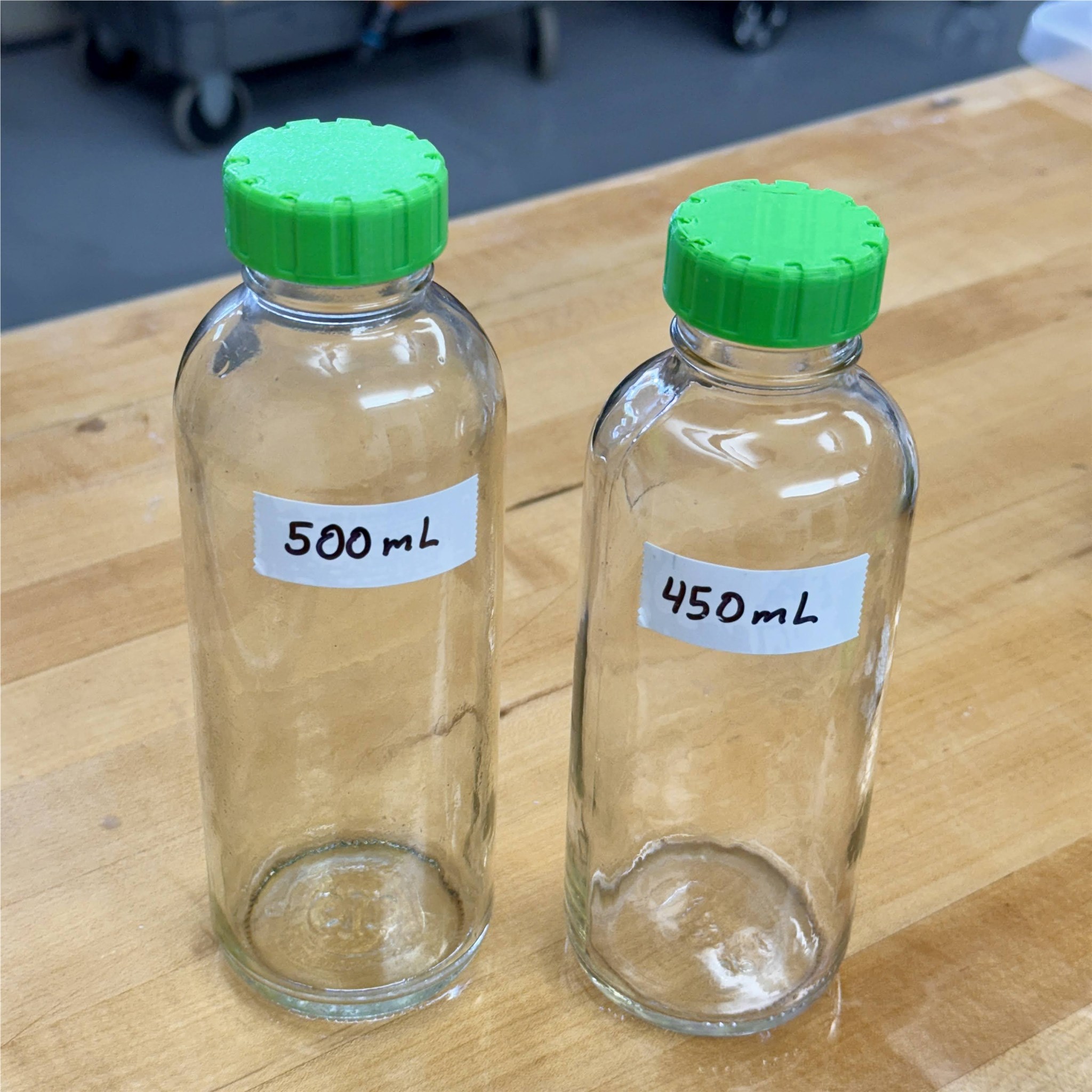
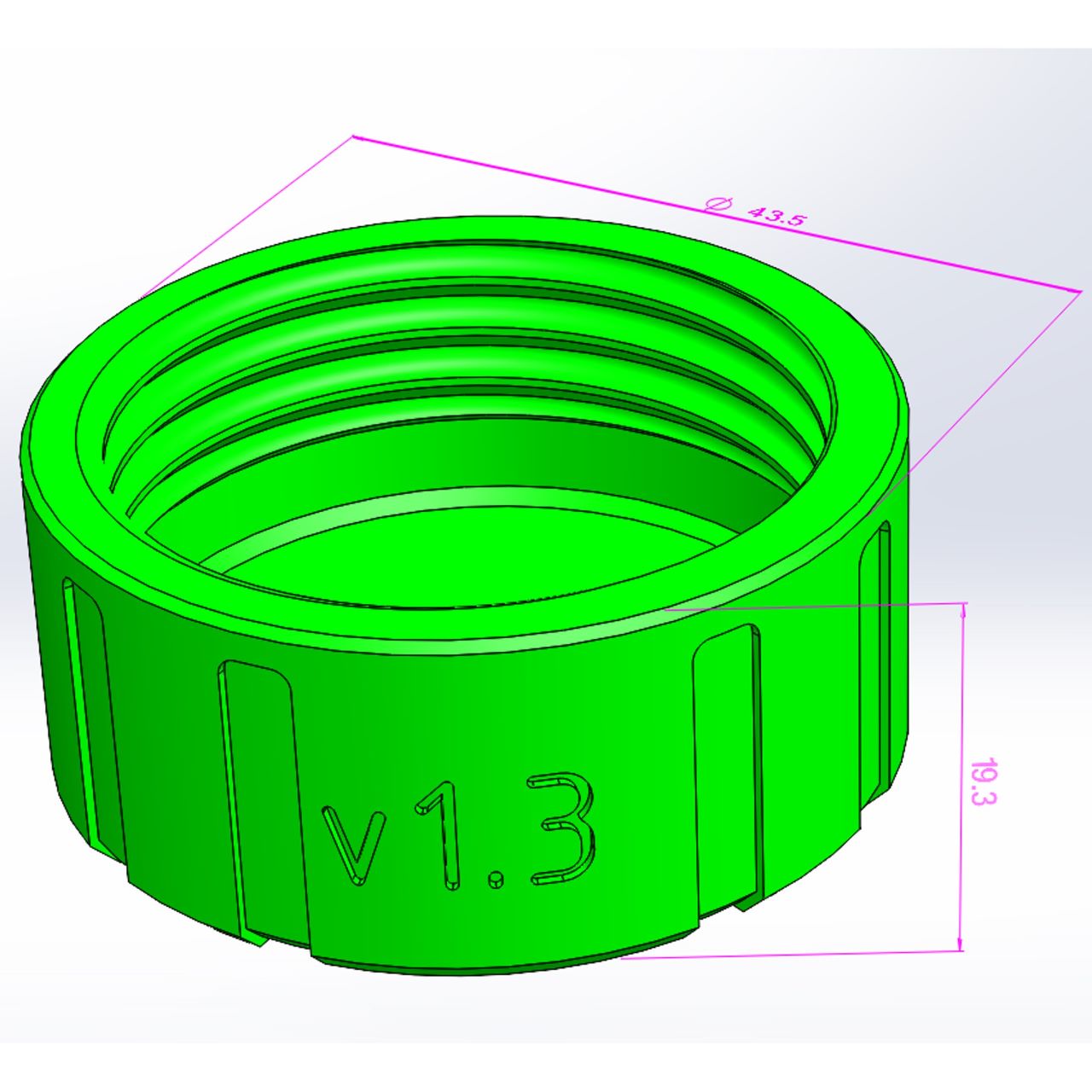
BottleCap
A threaded cap for glass bottles. Adjust the size to fit a new bottle. Adjust the thread to make a new (but still printable) thread. Add a sealing feature to gain airtightness. Study the design tree to learn to make threads in Solidworks. This design is intended for many different purposes. In the example, the purpose is fitting this cap to a drink bottle, for a result that is more re-usable, more customizable, more durable, and gives control over color to the user. Implement an off-the-shelf seal for surefire watertight and airtight sealing. The printed threads tolerate a strong tightening torque but sealing is limited by the surface finish of the printed part. If you are designing for sealing threads, I highly recommend exploring this model and making a copy to learn from.
- buy foam seals, 35mm, on amazon here.
- download the cap model on GrabCAD with parametric solidworks model.
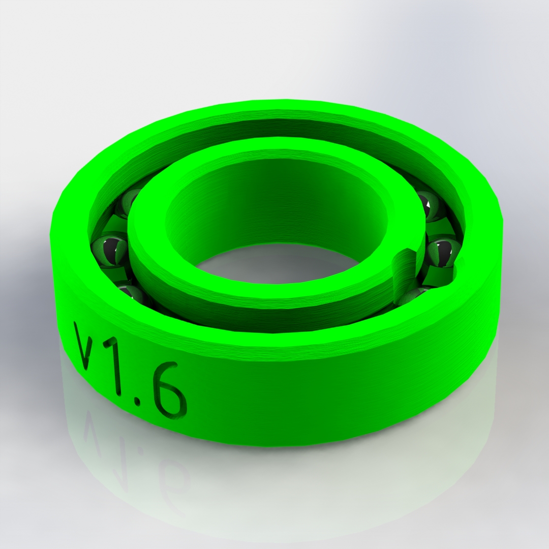
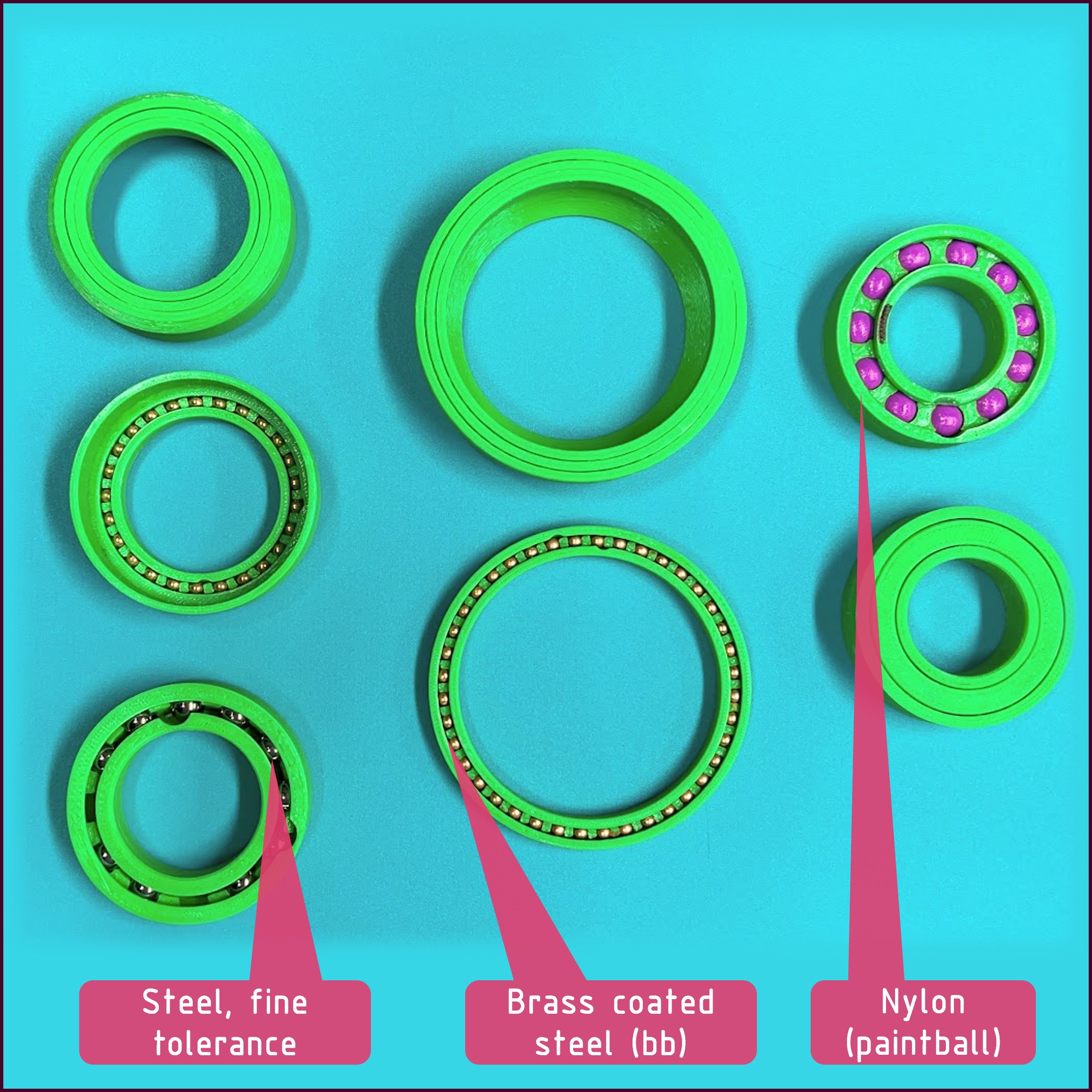
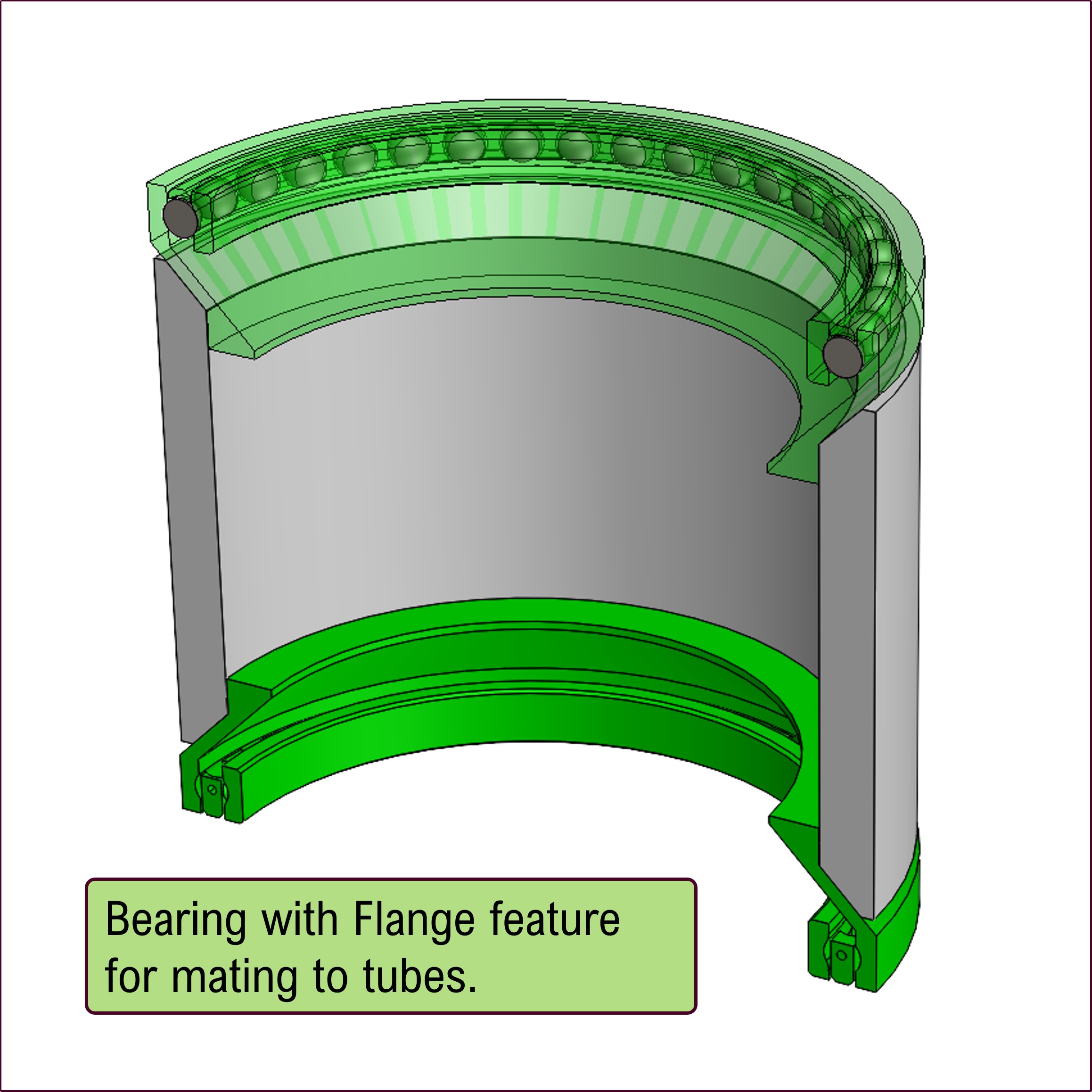
Bearing
This bearing is: A functional load-bearing design with print-in-place geometry. A low-cost bearing which accepts many sizes of balls, and many materials. A parametric part which can be adjusted for inner diameter, outer diameter, and width to mate any pair of round geometries. A desich which can bond permanently to a matching PVC tube for permanent integration. The design has so many utilities that a repository, OpenSpin, was initiated to expand the documentation.
- download the CAD model for the bearing on grabCAD
- watch short video "borrow a tolerance"
- watch short video "use balls"
RollerBracket
A tested & validated design to attach wheels to your 3030 aluminum extrusion. It includes two fasteners, carries a 6mm center pin, and accomodates a common OTS skate wheel with the high strength & durability of urethane. These rollers are used in the lab for custom built racks and holding up for 3+ years.
- download roller bracket model and see the third photo showing M8 fastener which threads into the end of the extrusion.
- watch short video roller bracket
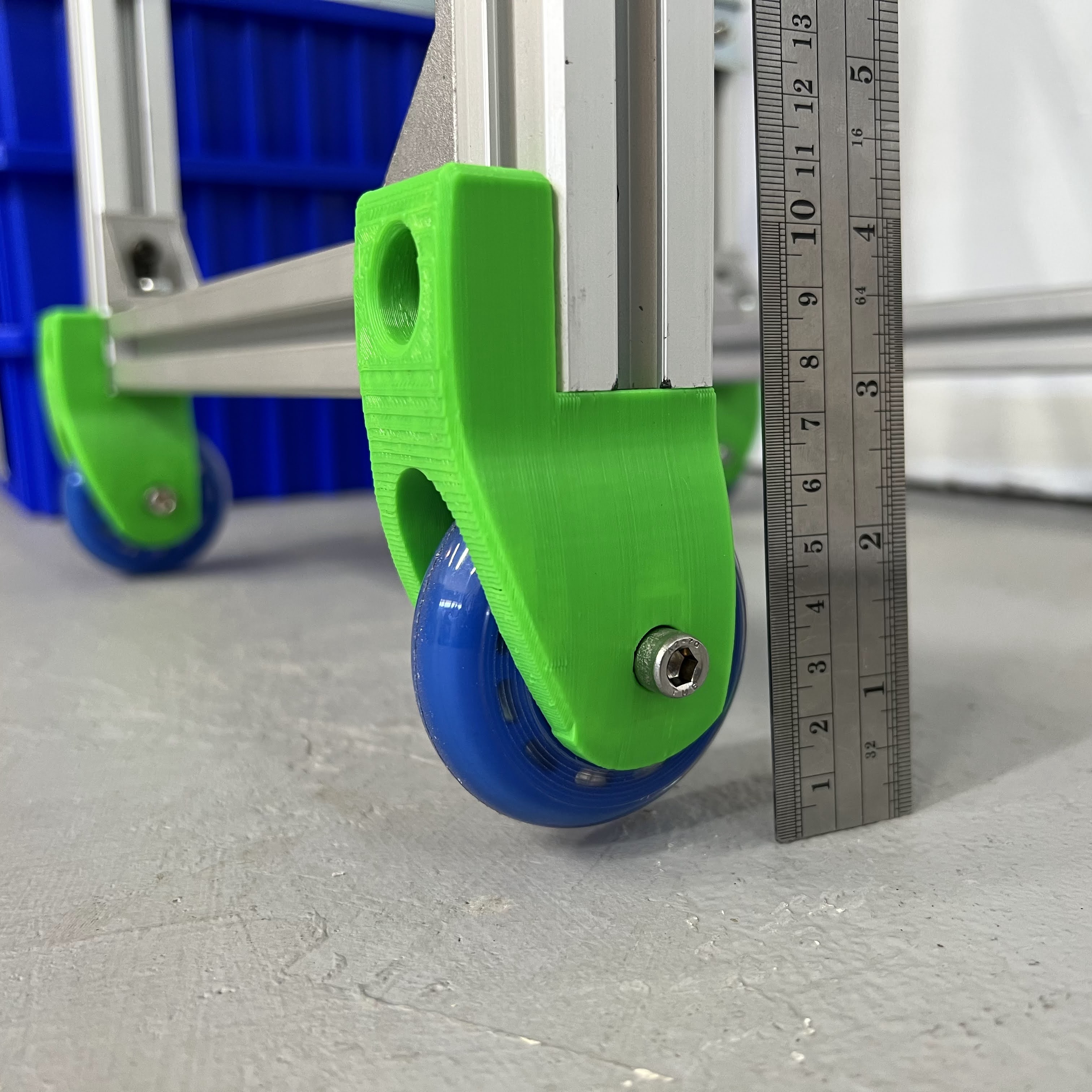
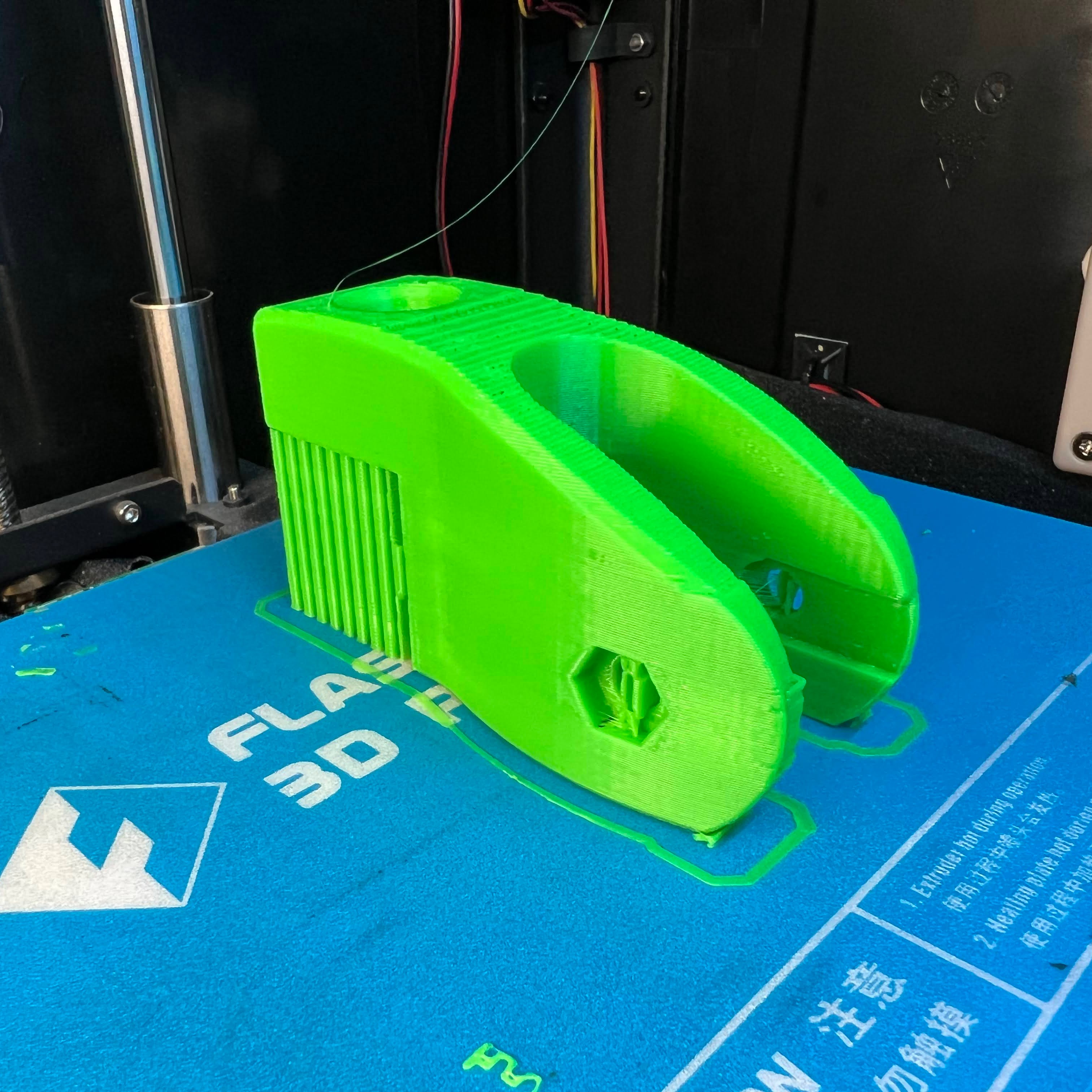
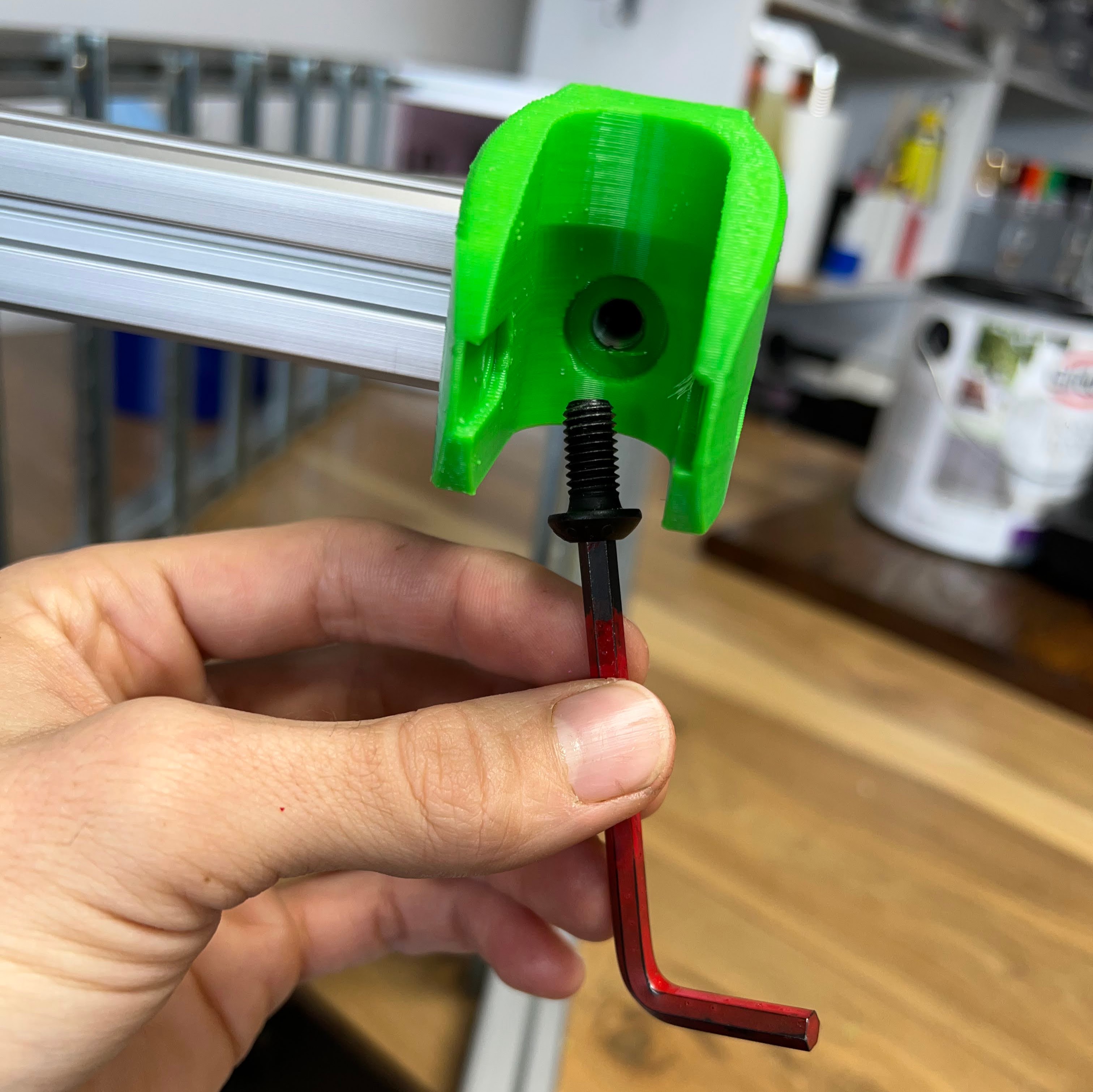
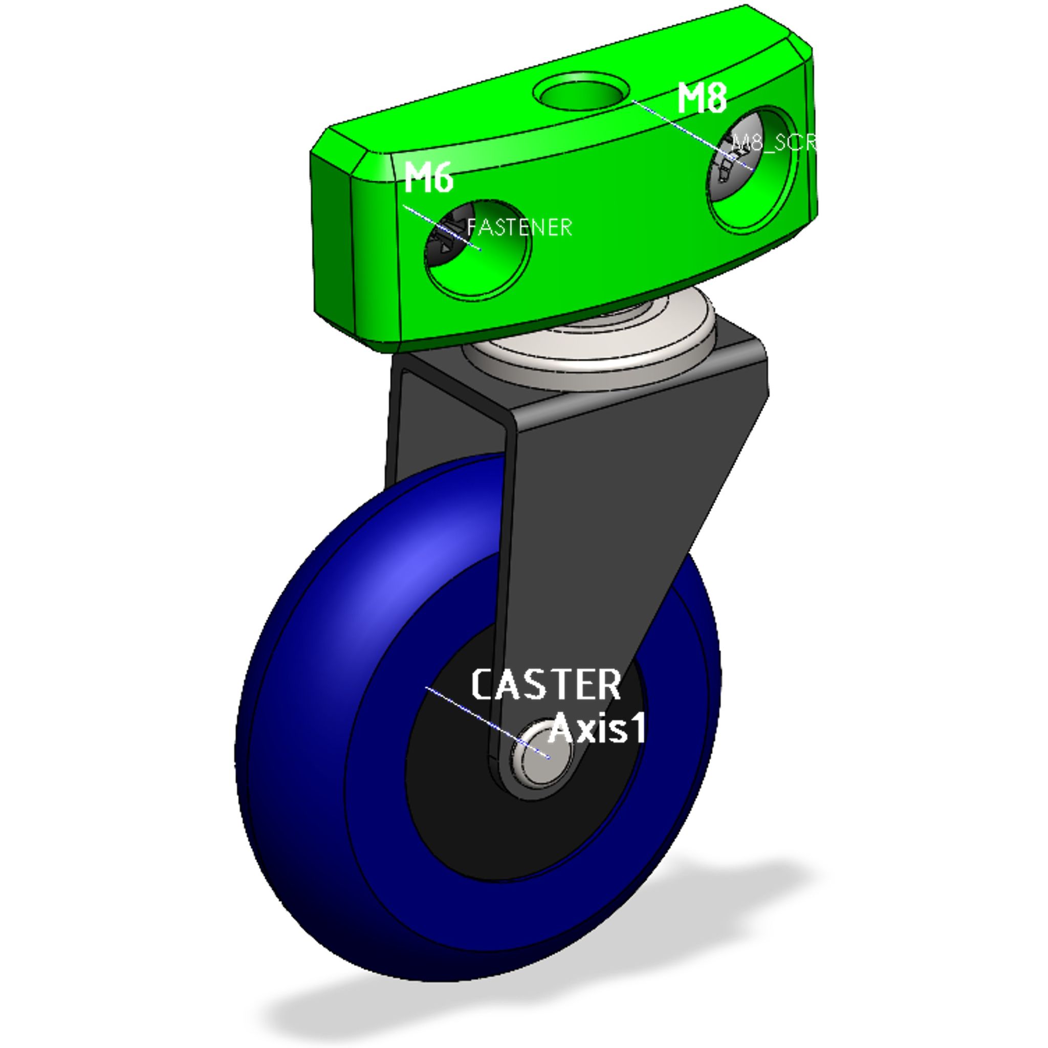
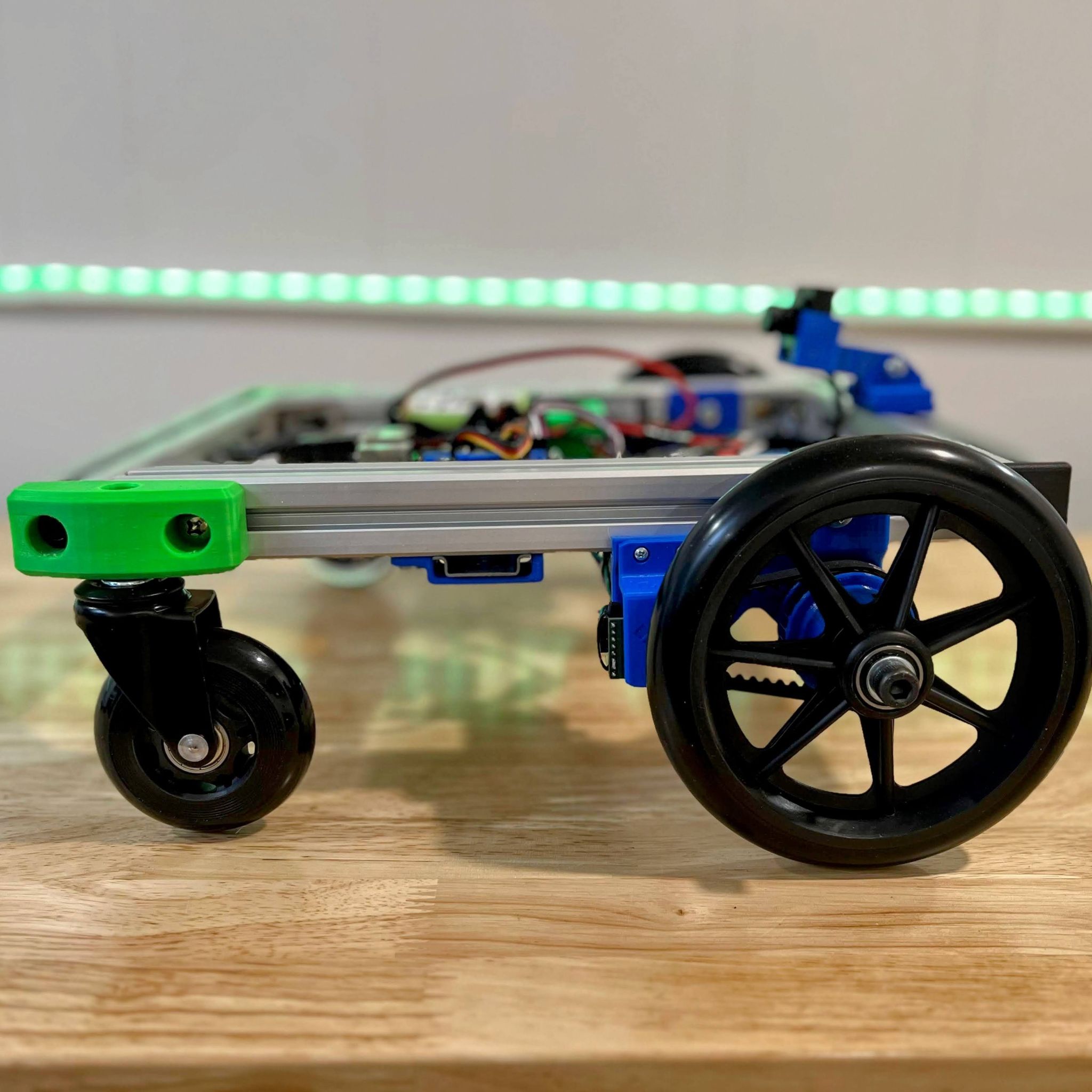
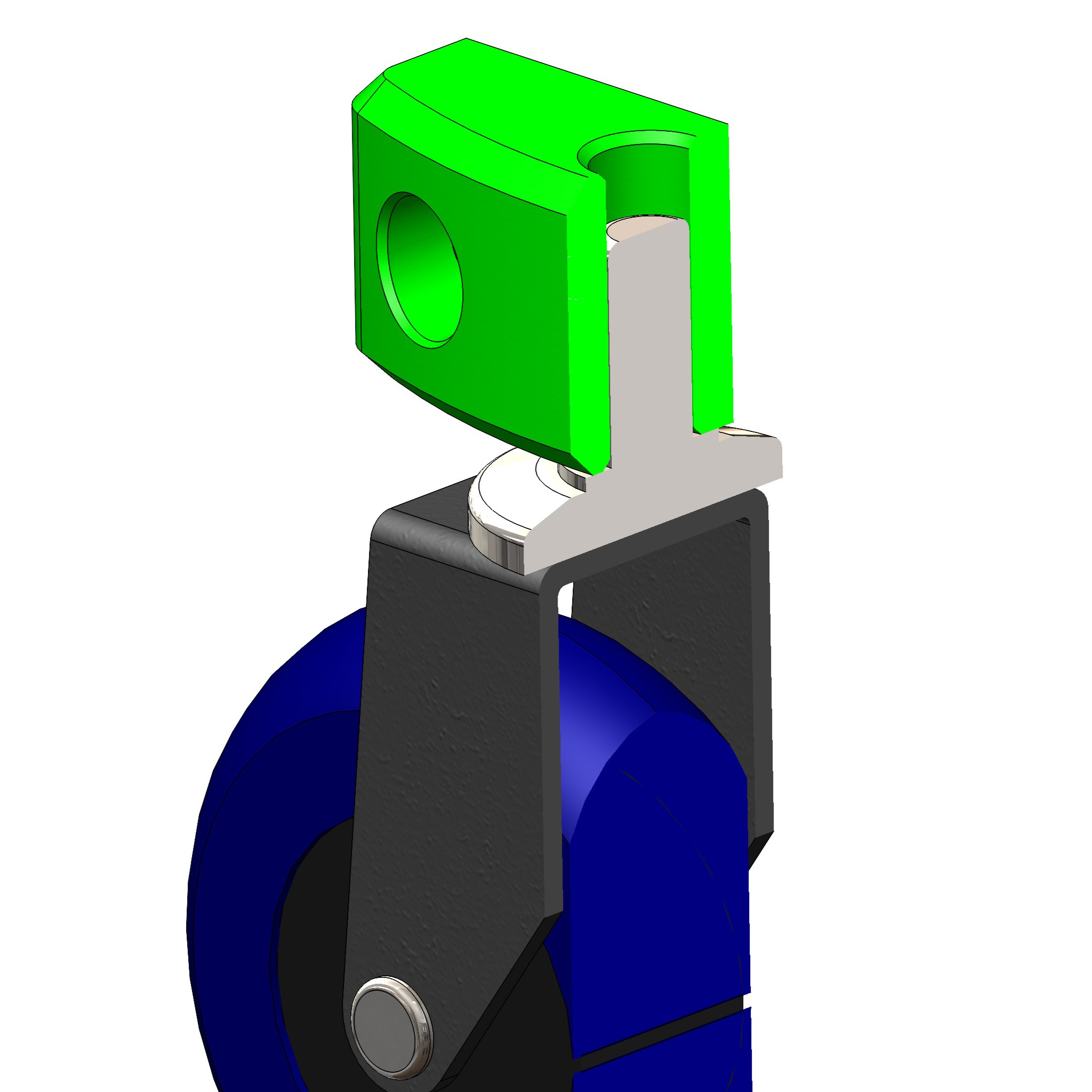
Caster
A caster bracket for implementing the very popular OTS casters having 76mm diameter wheel and a snap-in pin. These are so popular that you can sometimes find the whole caster assembly (minus this 3D printable bracket) for a lower cost than a wheel, per piece. Modern versions have a heavy urethane wheel, good quality bearings, and stamped steel fork with a steel hinge-pin and ball-bearing pivot. That is, two degrees of freedom for your rolling chassis and we can reliably accomodate these into a 3D print without any postprocessing. The pin fits vertically while two horizontal holes guide your M6 fasteners into aluminum rail or other chassis material.
- download caster CAD model on grabCAD
- buy casters on amazon at $20/5pk
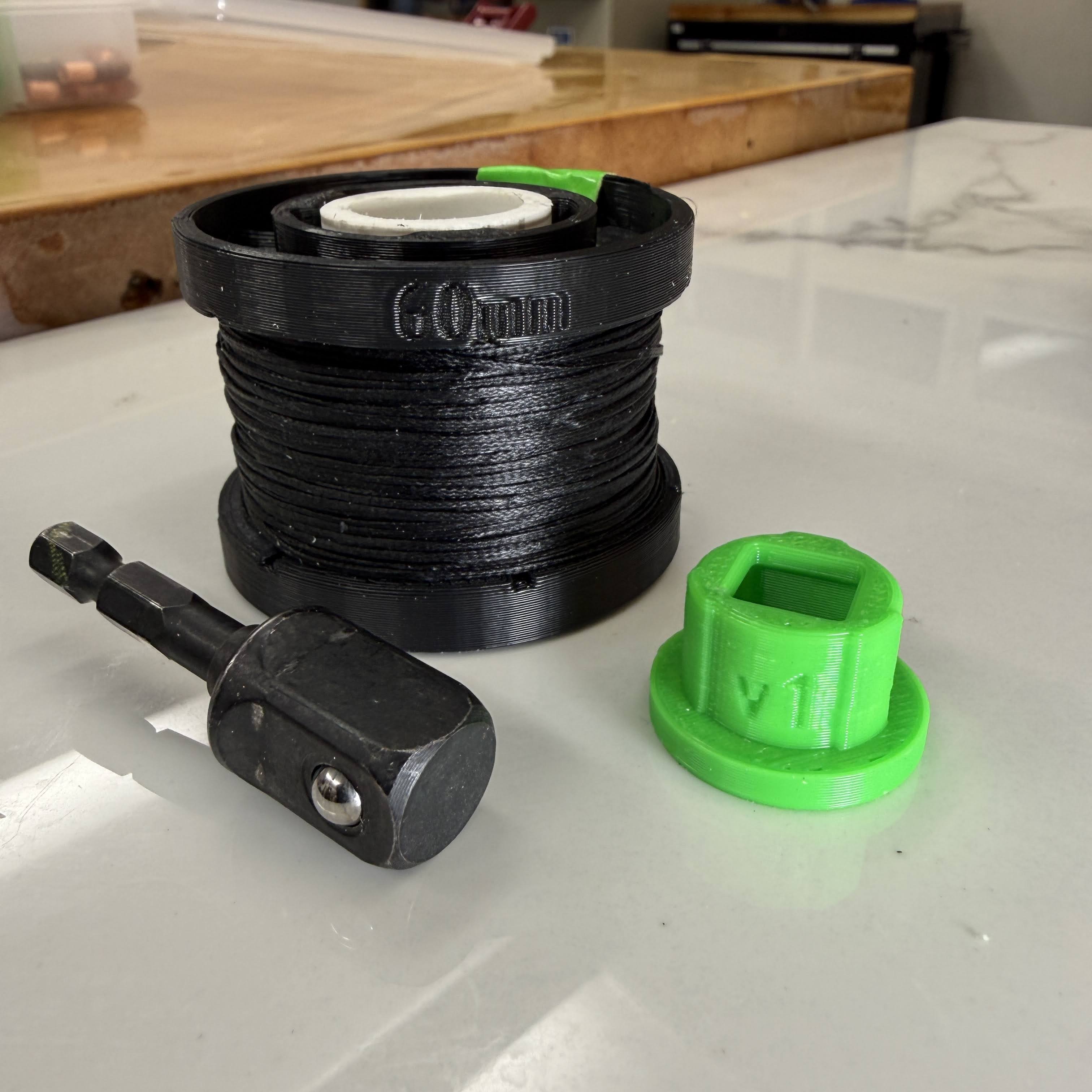
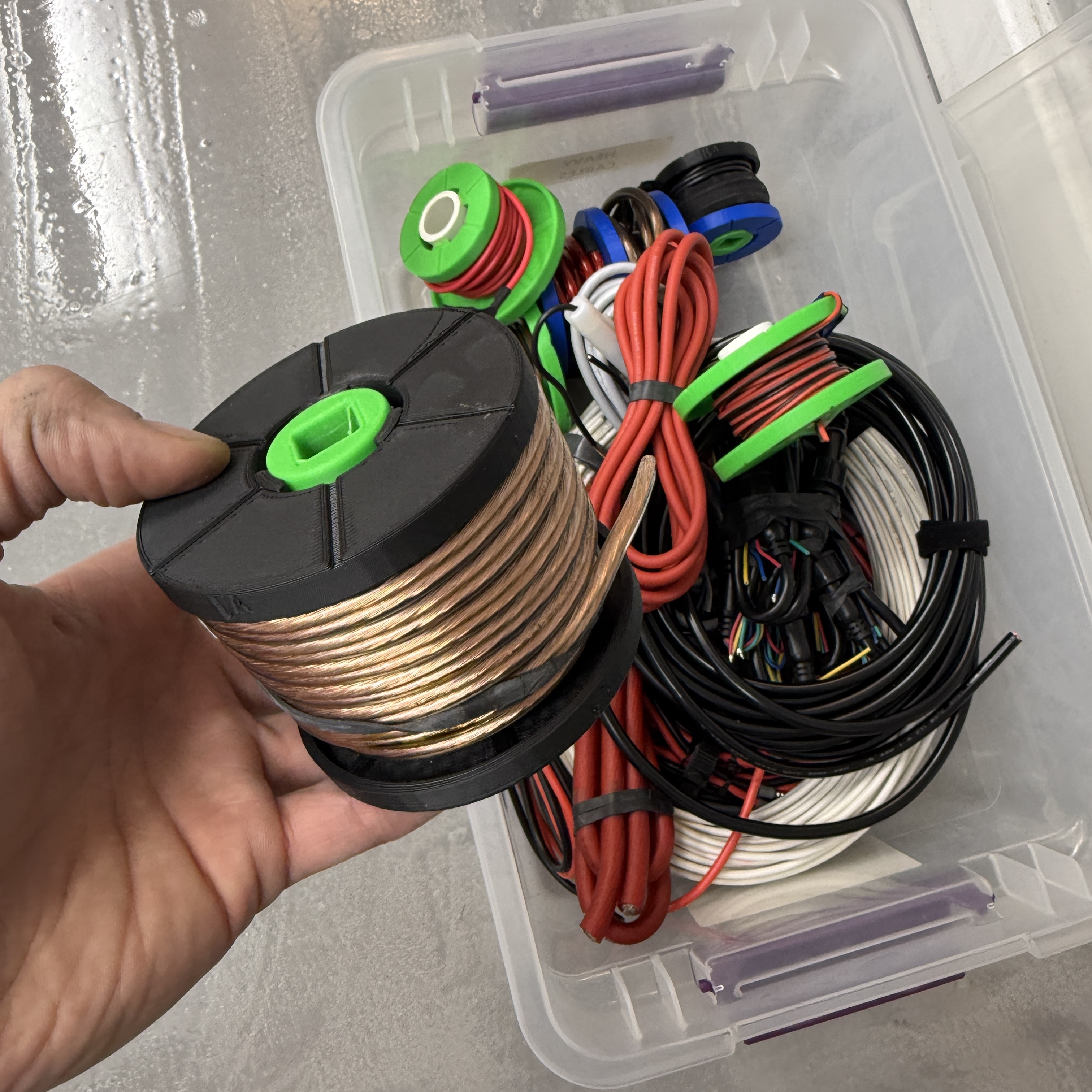
Spool
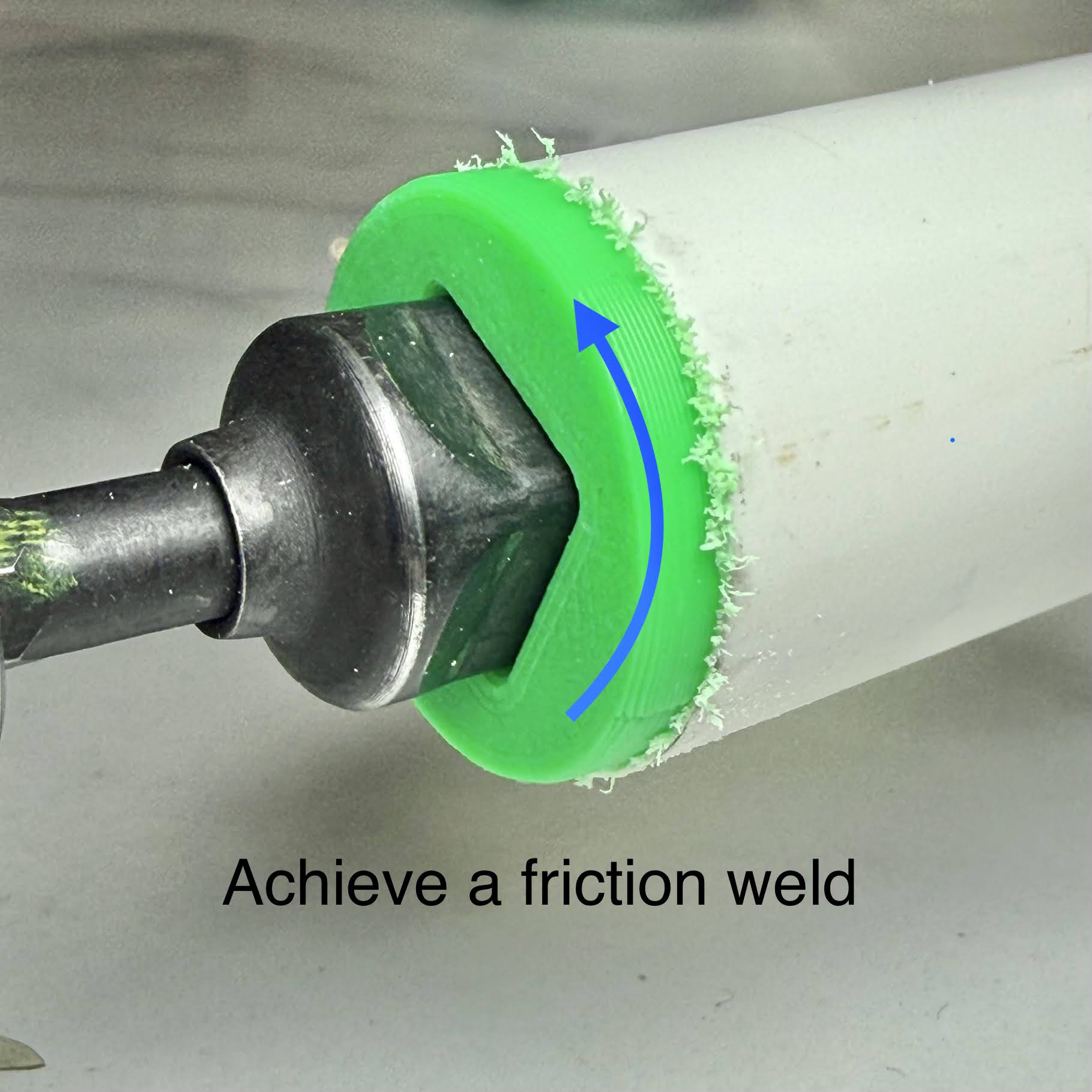
This spool offers customization and a simple storage solution for cord supplies. You can coil up loose cables on the spool with a power drill, using a 1/2in drive adapter on an electric impact driver or drill. The two side panels print separately, and press-fit onto a segment of PVC pipe. Use 3/4in PVC pipe which is very economical at around $5 for 10 feet. For bonding: you can leave the side panels unbonded and they are secure with friction only. For the impact drive adapter, this can be mated to the PVC with CA glue or by friction welding. To friction-weld, mate the adapter to the PVC and hold the PVC steady (glove for safety) with about 2 seconds of rapid turning of the adapter. The plastic heats up and bonds together. If you omit the drive adapter, the PVC spools rack neatly on steel EMT conduit, size 1/2in. This PVC is SDR21 specification which has an OD of 26mm and is rated for 200 PSI.
- download spool CAD model on grabCAD
- find pvc 3/4in specifications at lowes
Can_Rack
The canRack is a printable part combined with a steel wire to retain cans while leaving the labels visible. Keywords: can holder, spray can, mount, bracket, organizer. The rack mounts onto DIN rail (with or without fasteners) and prints with minimal material and a simple interface to DIY the wire into place. For fastener, use our common M6x12 machine screw, and without fasteners the DIN rail must face flanges-forward just like the typical electronics setup. Find instructions in the grabCAD post for bending the wire. With a little practice the wire bending is easy, but essentially you need 2 segments turned at 90 degrees from the main hoop which retains the can. HELP WANTED: the next need is to build a variation that holds the smaller common can size, so please share if you design this mod!
- download canRack on grabCAD
- find stainless steel wire, 2mm on Amazon


The printegrated examples above have several purposes in parallel. The models aim to answer the following needs & questions:
- Where can designers find engineering-grade example designs and explore the source files, CAD models?
- Where can you find a collection of physical parts to build a multidisciplinary laboratory?
- Where can we see best practices for design-for-manufacturing of 3D printable parts?
- For parametric designs, what are good choices of parts that don't have OTS solutions and benefit from added effort to make them parametric?
- What are good practices for fully documenting a mechanical design? (see the structure of the photos, images, grabCAD post, and file types).
- For researchers who are authoring on the topics of parametric models, printable designs, or functional testing of 3D parts, what are some online models that are actively supported by a potential co-author?
- How can an author support maintaining a design with updates & changes just like software developers do with code? (see how these models update over time, with version numbers etc.)
Watch the video about value breakdown for more explanation.
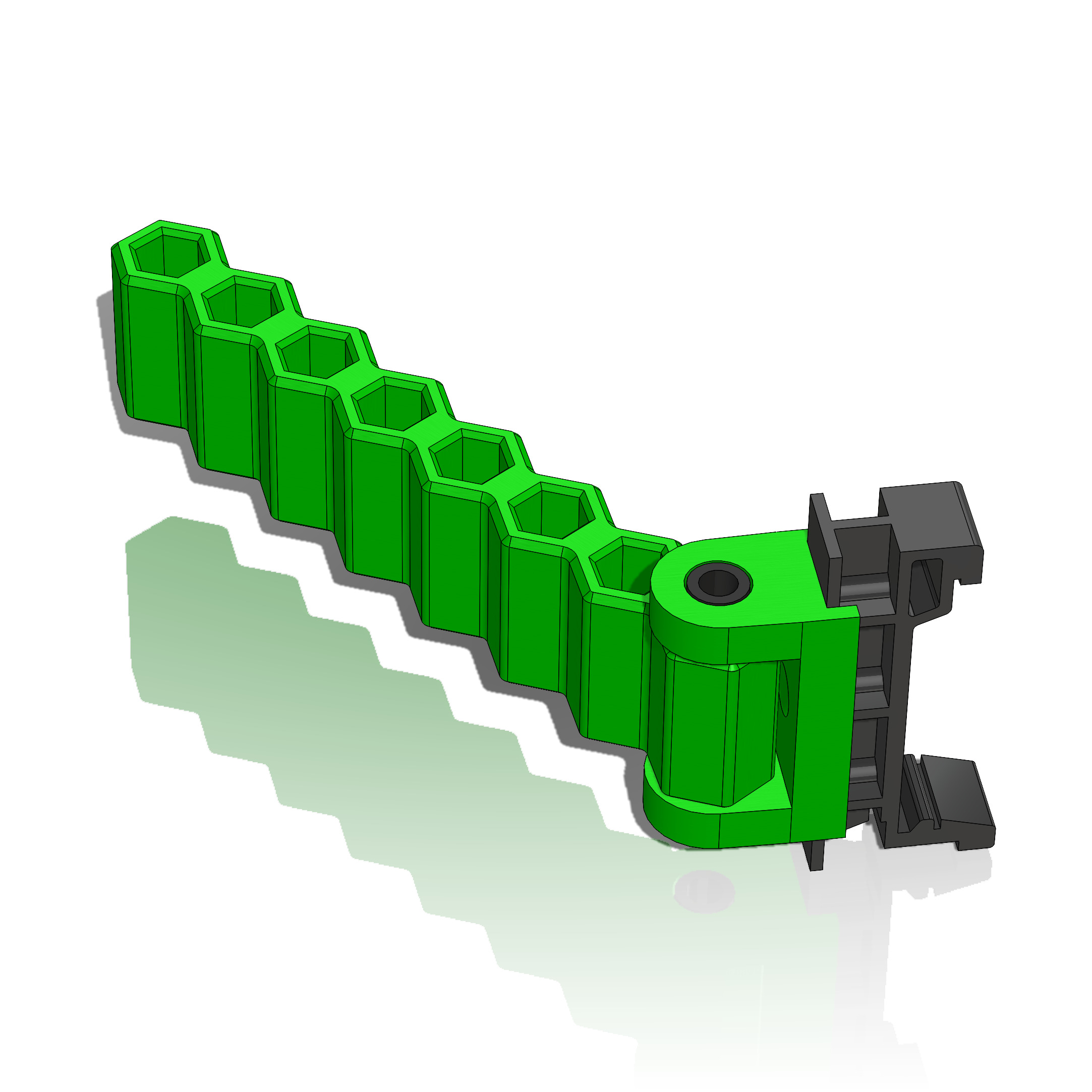
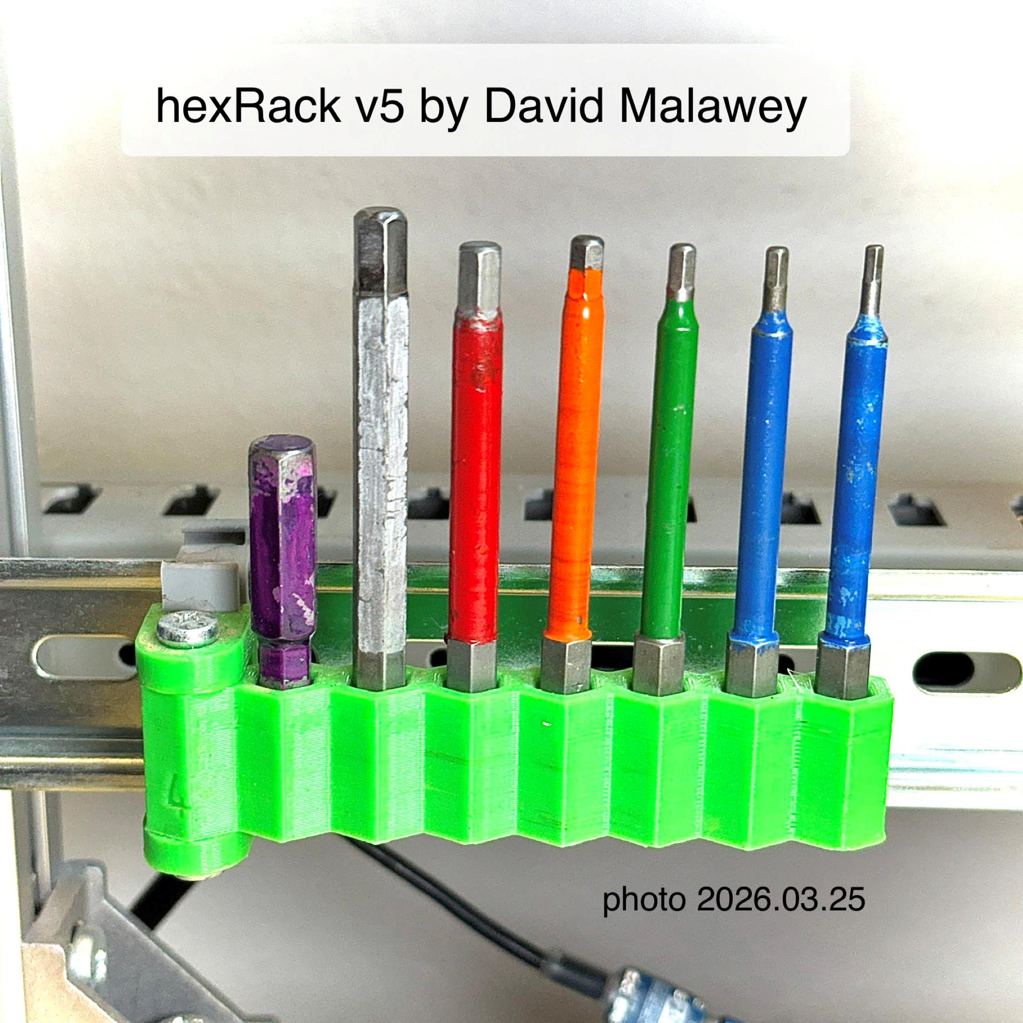
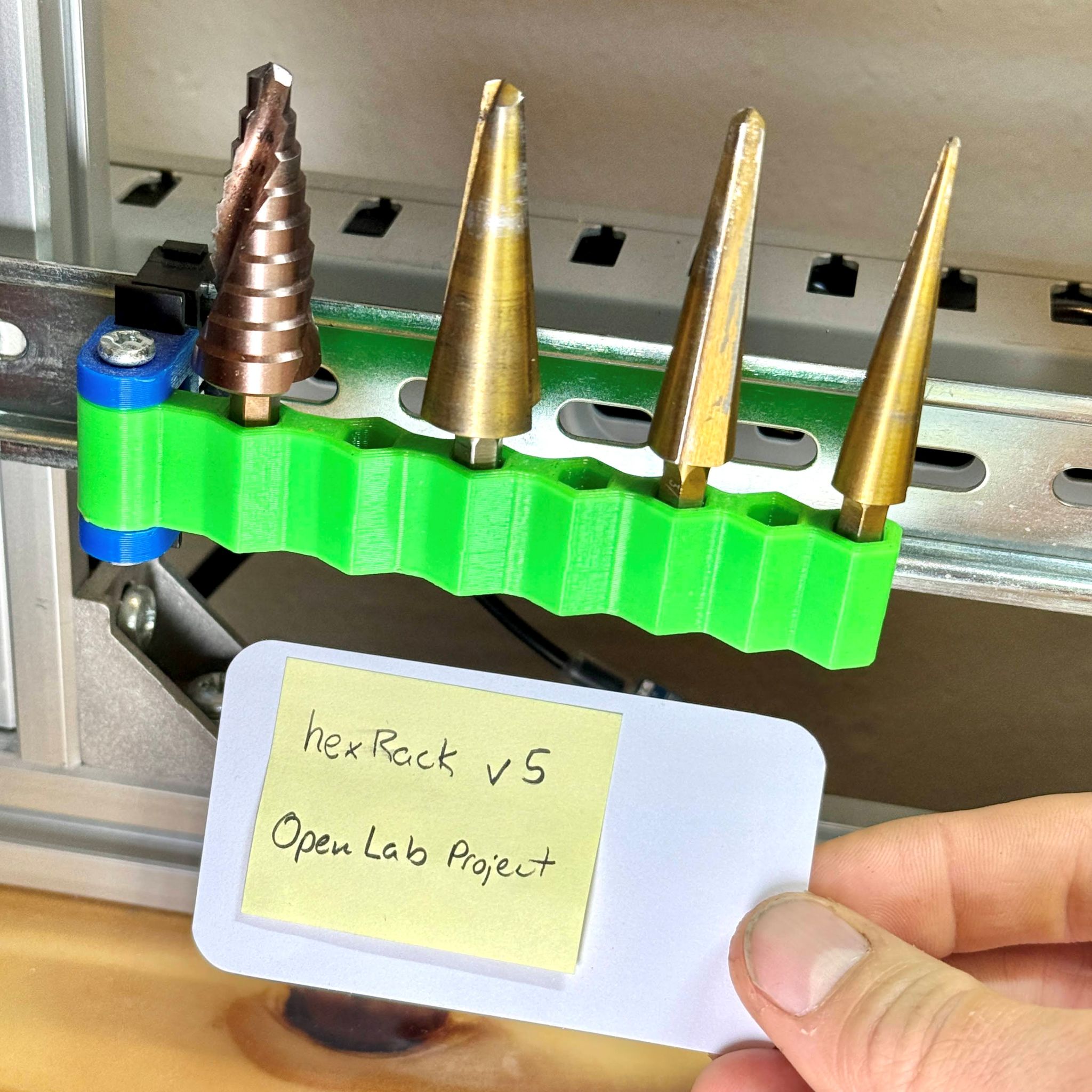
<iframe width="600" src="https://www.youtube.com/embed/IvZXdxWh7dg" title="How to solve a simple 60 year old problem" frameborder="0" allow="accelerometer; autoplay; clipboard-write; encrypted-media; gyroscope; picture-in-picture; web-share" referrerpolicy="strict-origin-when-cross-origin" allowfullscreen></iframe>HexRack is a frequently requested part used throughout the lab. I did not publish it until 2026.03 because it has many variations, and users may want different options. So the selected "main" variation is called version 5, with 7 slots and the STL folder in the grabCAD post has several variants. This rack holds driver bits, and many more hex-shanked tools in the lab.
- download hexRack on grabCAD
- see youtube video on labeling which features this tool at around 2:30 minutes mark.